Variable bandwidth transimpedance amplifier with one-wire interface

a transimpedance amplifier and variable bandwidth technology, applied in the field of optical transceivers, can solve the problems of affecting the performance of the receiver,

Inactive Publication Date: 2006-03-02
MICROSEMI STORAGE SOLUTIONS
View PDF13 Cites 34 Cited by
  • Summary
  • Abstract
  • Description
  • Claims
  • Application Information

AI Technical Summary

Benefits of technology

[0012] Another aspect of the invention provides a method of operating a receiver optical subassembly, comprising generating a current signal in response to a data bearing incoming light signal; providing the current signal to a transimpedance amplifier; forming a signal indicative of the current signal; placing the signal indicative of the current signal on a monitor / select pin; receiving a control signal on the monitor / select pin; adjusting an aspect of the transimpedance amplifier based on the control signal.
[0013] These and other aspects of the invention are more readily understood on review of the figures and text herein.

Problems solved by technology

Amplification of the signal is often problematic as the amplification often distorts and adds noise to the signal.
Transimpedance amplifier design often involves a number of trade-offs, where improvement in one area results in degradation in another.
For example, improvement in output signal quality may sometimes be achieved by limiting the useful bandwidth of the device.
Unfortunately, the use of a transimpedance amplifier optimized for a specific bandwidth generally implies that a receiver unit using the transimpedance amplifier may only be used in a system receiving data approximate the specific bandwidth.
This reduces flexibility in the use of receiver units and increases inventory stocking costs.

Method used


Image

  • Variable bandwidth transimpedance amplifier with one-wire interface
  • Variable bandwidth transimpedance amplifier with one-wire interface
  • Variable bandwidth transimpedance amplifier with one-wire interface

Examples


Embodiment Construction

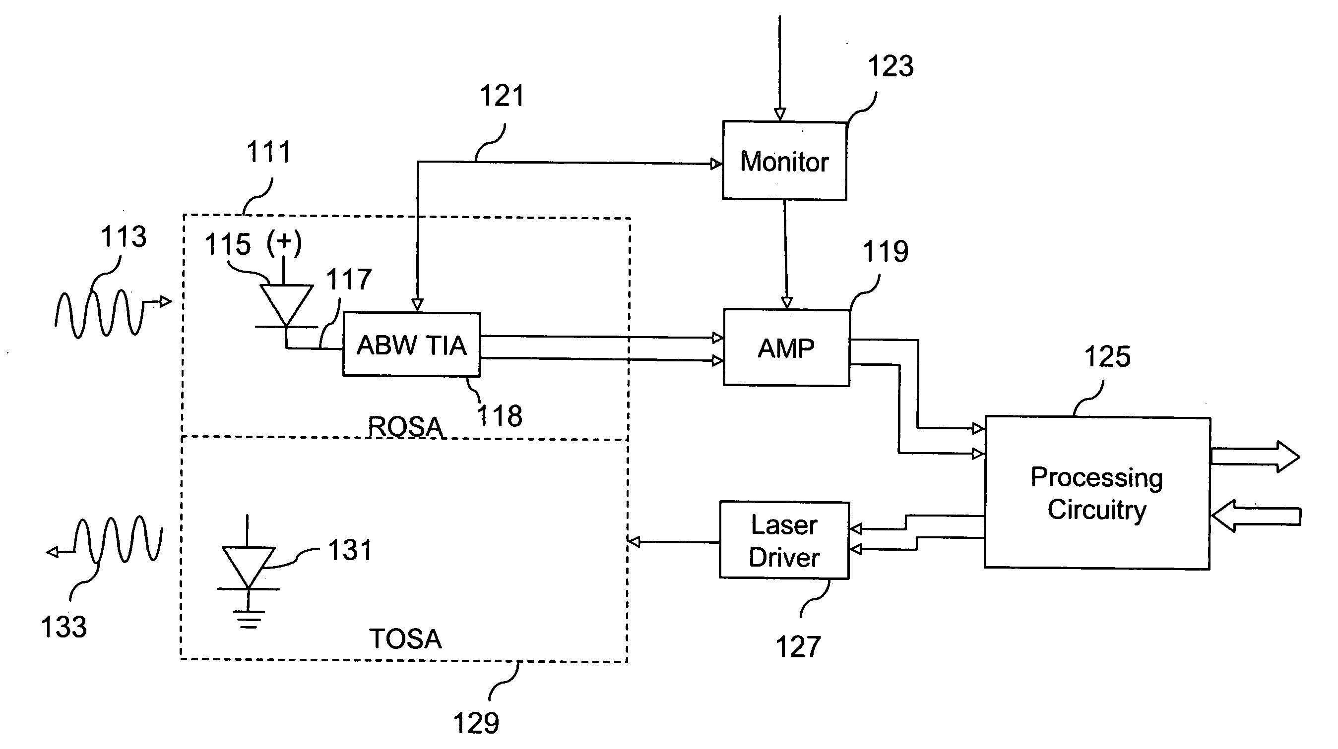
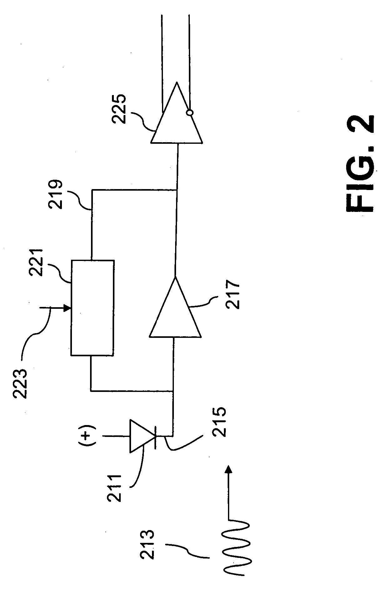
[0018]FIG. 1 is a block diagram of a transceiver with an adjustable bandwidth transimpedance amplifier in accordance with aspects of the invention. A receiver optical subassembly (ROSA) 111 receives an optical signal 113. The optical signal impinges on a photodetector 115 in the ROSA, generating a current signal on an output 117 of the photodetector. The photodetector of FIG. 1 provides a single output, although in various embodiments a differential output is provided.

[0019] The current signal is received by an adjustable bandwidth transimpedance amplifier block 118. The adjustable bandwidth transimpedance amplifier block converts the current signal to a voltage signal and amplifies the voltage signal. The adjustable bandwidth transimpedance amplifier block generates a differential voltage signal, which is provided to with a post-amp amplifier 119. In some embodiments the adjustable bandwidth transimpedance amplifier block provides a non-differential output signal, and in some embo...


PUM


Abstract

A bandwidth adjustable transimpedance amplifier. The bandwidth adjustable transimpedance amplifier includes a feedback path with a selectable resistance. The bandwidth adjustable transimpedance amplifier is preferably implemented with a photodiode in a five pin package for an optical transceiver system, with a single pin providing a monitor out function and a rate select input.

Description

CROSS-REFERENCE TO RELATED APPLICATION(S) [0001] This application claims the benefit of the filing date of U.S. Provisional Patent Application No. 60 / 604,337, filed Aug. 25, 2004, the disclosure of which is incorporated by reference herein.BACKGROUND [0002] The present invention relates generally to an optical transceiver, and more particularly to a receiver optical subassembly with an adjustable bandwidth transimpedance amplifier in an optical transceiver. [0003] Optical transceivers are often used in optical communication systems. Optical transceivers transmit and receive optical information generally at very high data rates. In many applications the optical information is formed by modulating light from a laser, either by direct modulation of the laser or by using a separate modulator, such as an electroabsorbtion modulator or a lithium niobate modulator. The modulated light is passed over a fiber optic line, often simultaneously with light from other lasers at varying wavelength...

Claims


Application Information

Patent Timeline
Patent Type & Authority Applications(United States)
IPC IPC(8): H04B10/00
CPCH03F3/087H03F1/34
Inventor KILLMEYER, SCOTTCHOI, LAWRENCEXU, YANZHEN
Owner MICROSEMI STORAGE SOLUTIONS
Why Eureka
Try Eureka