Air compressor tools that communicate with an air compressor

a technology of air compressor and tool, applied in the field of power tools, can solve the problems of confusing the existence of both the tank pressure and line pressure gauge, confusing the new user, and difficult to adjust to the desired output pressur

Inactive Publication Date: 2006-03-02
DEVILBISS AIR POWER COMPANY
View PDF40 Cites 36 Cited by
  • Summary
  • Abstract
  • Description
  • Claims
  • Application Information

AI Technical Summary

Benefits of technology

[0014] In accordance with an embodiment, a pneumatically controlled regulator is provided for controlling output pressure for an air compressor. In an embodiment, the pneumatically controlled regulator utilizes a pneumatic controller that provides air on the back side of a cylinder for a regulator. Varying the air pressure provided by the pneumatic controller provides a similar function to the fixed rate spring and variable knob of prior art regulator designs. Thus, the pneumatic controller functions as an air spring. By increasing or decreasing the air pressure on the back side of the piston for the regulator, the pneumatic controller can control the pressure in the cylinder and thus control the output pressure of the air compressor. In an embodiment, the air pressure is controlled electronically via an easily understood user interface.
[0016] In accordance with an embodiment, an air compressor includes digital gauges to replace conventional mechanical gauges. In addition, a user interface for the air compressor may include presets for selected operating pressures, an indicator to show what operating pressure at which the air compressor is operating, and / or pressure selector buttons for increasing or decreasing the pressure. The digital display may show both regulator and tank pressure, or may be switched to show only one, eliminating confusion for many users.
[0019] In an embodiment, the signal provided by the tool is a resistance provided by the tool in a circuit that includes a resistor. The air compressor utilizes a lookup table to determine the necessary operating functions of the air compressor with respect to the resistance provided by the tool. In an embodiment, the tool may include a rheostat that allows the user to vary the resistance and thus change the operation of the air compressor.

Problems solved by technology

Although conventional air compressors work well for their intended purpose, the existence of both the tank pressure and line pressure gauges may be confusing to a new user.
The variable knob and fixed rate spring may also be confusing, and may be difficult to adjust to a desired output pressure.
Another problem inherent in the design of the mechanical gauges is that the gauges are susceptible to vibration, which all air compressors have.
Vibration sometimes makes the mechanical pressure gauges on conventional air compressors difficult to read.
One downside to electrical air compressors is that they must be designed to operate at conventional circuit levels.
Designing a conventional air compressor within the limits of existing circuits can cause limitations in the performance of a conventional air compressor.
Higher pressures require more power to run the pump, and result in loading the motor to higher horsepower levels.
Since the air compressor is limited to an electric circuit of a certain size, the overall performance of the machine is limited based on the peak amperage used at the maximum load.
Due to manufacturing tolerances causing some degree of variation in the load from air compressor to air compressor, most conventional air compressors are not designed at the absolute maximum performance (i.e., 15 amps).
Thus, many air compressors are not capable of drawing amps that are available for the air compressor.

Method used


Image

  • Air compressor tools that communicate with an air compressor
  • Air compressor tools that communicate with an air compressor
  • Air compressor tools that communicate with an air compressor

Examples


Embodiment Construction

[0041] In the following description, various embodiments of the present invention will be described. For purposes of explanation, specific configurations and details are set forth in order to provide a thorough understanding of the embodiments. However, it will also be apparent to one skilled in the art that the present invention may be practiced without the specific details. Furthermore, well-known features may be omitted or simplified in order not to obscure the embodiment being described.

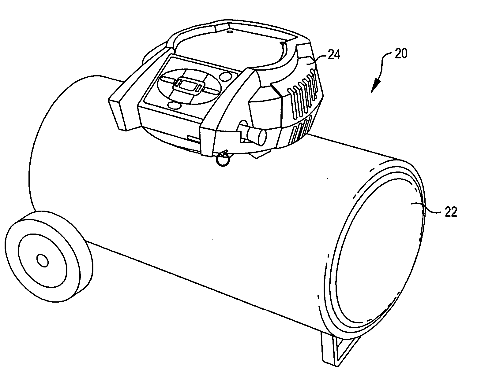
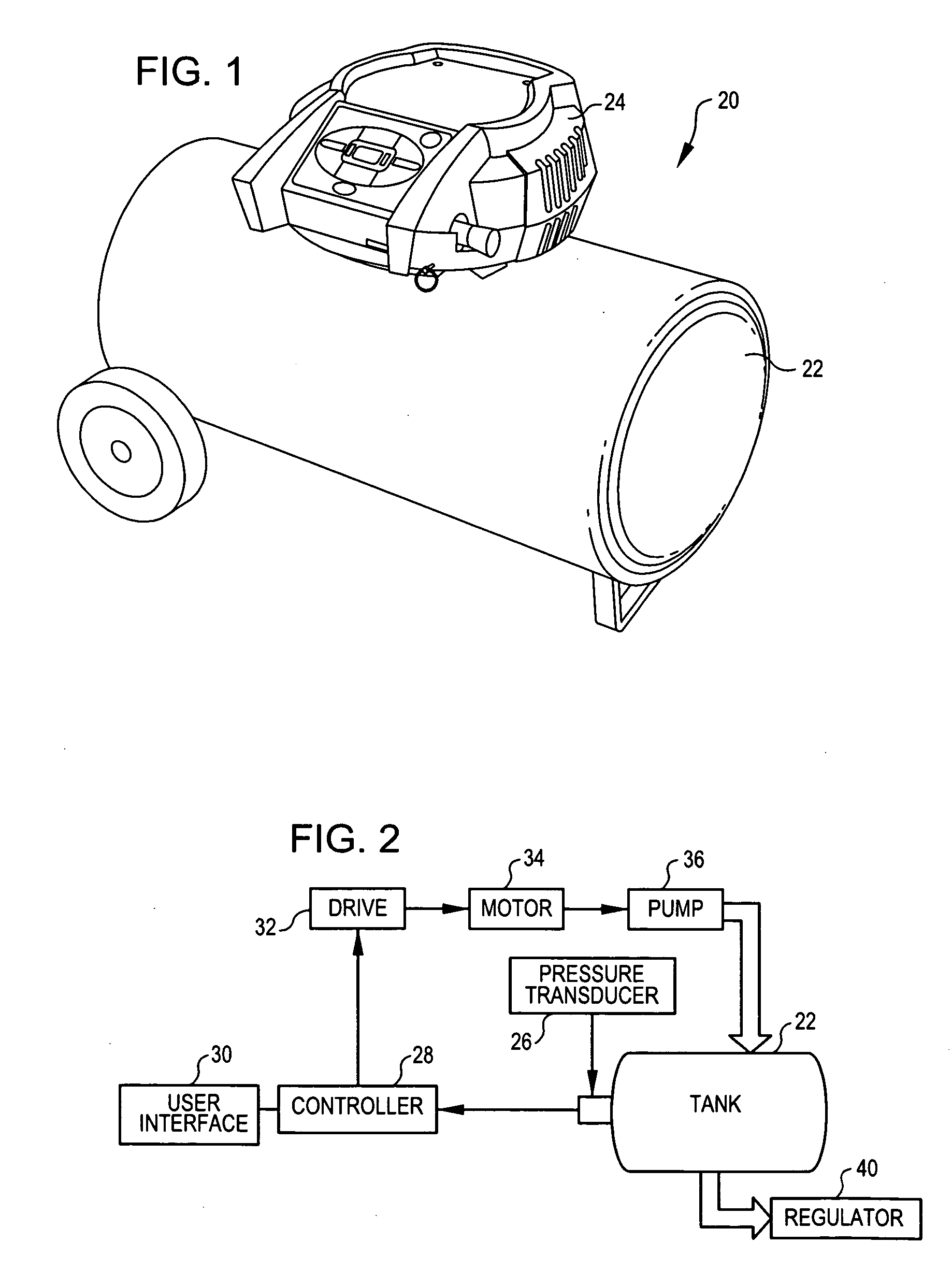
[0042] Referring now to the drawings, in which like reference numerals represent like parts throughout the several views, FIG. 1 shows an air compressor 20 incorporating aspects of the present invention. The air compressor 20 includes a tank 22 with a shroud 24 mounted thereon. Internal components are mounted in the shroud 24, one embodiment of which is shown diagrammatically in FIG. 2.

[0043] The tank 22 for the air compressor 20 is, for example, a 20-gallon cylindrical compressor tank. The tan...


PUM


Abstract

An air compressor utilizing an electronic control system. A pneumatically controlled regulator is provided for controlling output pressure for an air compressor. Digital gauges are provided on the air compressor to replace conventional mechanical gauges. A variable speed motor is used, which in turn varies the speed of the pump. Tools are provided for an air compressor that are capable of transmitting a signal to the air compressor indicating a desired pressure and / or motor speed at which the air compressor is to operate.

Description

REFERENCE TO RELATED APPLICATIONS [0001] The present invention is related to United States patent applications entitled “AIR COMPRESSOR UTILIZING AN ELECTRONIC CONTROL SYSTEM” (Attorney Docket No. 306321) and “AIR COMPRESSOR WITH VARIABLE SPEED MOTOR” (Attorney Docket No. 306390),” having at least one common inventor, filed concurrently herewith, and hereby incorporated by reference in their entireties. TECHNICAL FIELD OF THE INVENTION [0002] The present invention relates generally to power tools, and more particularly to air compressors. BACKGROUND OF THE INVENTION [0003] Air compressors are becoming commonplace in home workshops. In general, an air compressor is a machine that decreases the volume and increases the pressure of a quantity of air by mechanical means. Air thus compressed possesses great potential energy, because when the external pressure is removed, the air expands rapidly. The controlled expansive force of compressed air is used in many ways and provides the motive...

Claims


Application Information

Patent Timeline
Patent Type & Authority Applications(United States)
IPC IPC(8): F04B49/06F04B17/00
CPCF04B41/02F04B2203/0209F04B49/065F04B49/022
Inventor BECKMAN, KURT
Owner DEVILBISS AIR POWER COMPANY
Why Eureka
Try Eureka