Catalytic reactor

a catalytic reactor and reactor technology, applied in the direction of physical/chemical process catalysts, bulk chemical production, lighting and heating apparatus, etc., can solve the problems of heat transfer and thermal insulation, self-design limitation of unit operation or operation, etc., and achieve the effect of reducing the sulfur content within the hydrocarbon feed

Inactive Publication Date: 2006-03-02
PRAXAIR TECH INC
View PDF10 Cites 35 Cited by
  • Summary
  • Abstract
  • Description
  • Claims
  • Application Information

AI Technical Summary

Benefits of technology

[0018] Preferably, a sulfur treatment canister can be located within the central axial insulated chamber to reduce the sulfur content within a hydrocarbon feed. As will be discussed, the sulfur treatment canister can be a multiple layered system having a hydrotreatment catalyst and chemisorbent. The sulfur treatment canister is positioned so as to be surrounded by and insulated from the second set of heat exchange tubes. The sulfur treatment canister is interposed between the at least one reaction feed inlet and the inner tubes of the tube in tube heat exchanger such that the hydrocarbon feed is treated by conversion of the sulfur to hydrogen sulfide that is in turn converted into zinc sulfide and water prior to being introduced into the first reaction zone.

Problems solved by technology

However, the coiled tube design, while permitting the fabrication of a compact reactor, at the same time, is in and of itself a design limitation on the unit operation or operations to be conducted within the reactor.
Additionally, as the spiral is made longer to accommodate a longer length of tubing, even heat transfer and thermal insulation can become problematical because of the greater length over which heat transfer takes place and / or thermal insulation is provided.

Method used


Image

  • Catalytic reactor
  • Catalytic reactor
  • Catalytic reactor

Examples


Embodiment Construction

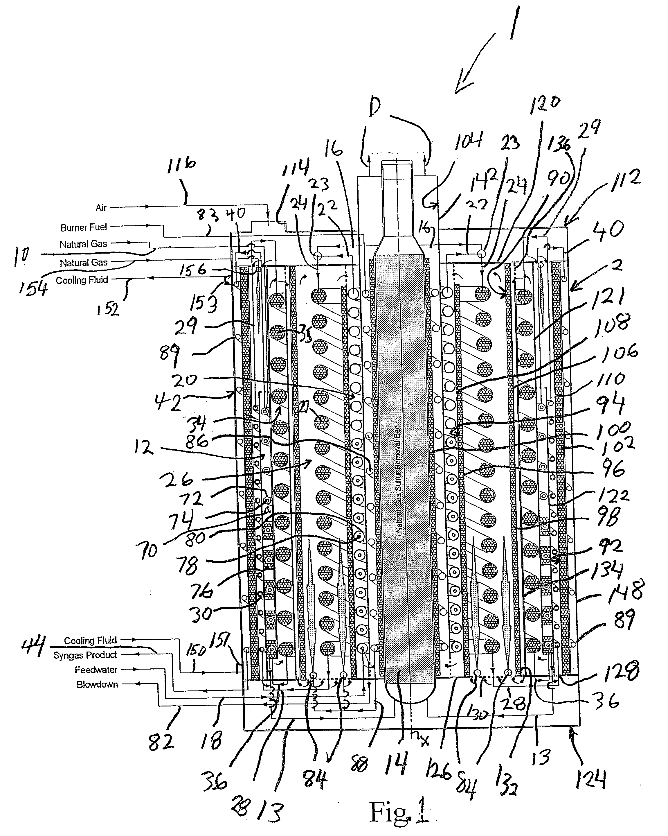
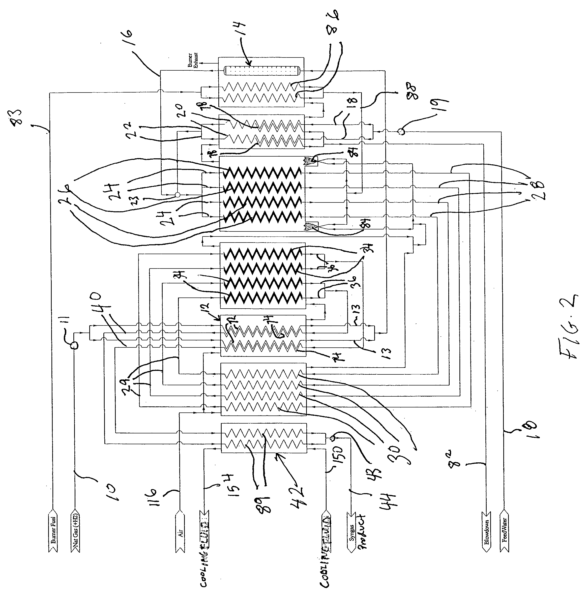
[0030] With reference to FIGS. 1 and 2, a catalytic reactor 1 of the present invention is illustrated that is specifically designed to produce a synthesis gas product that has a high concentration of hydrogen. As will be discussed, this is accomplished by steam methane reforming to produce an intermediate product stream which is subsequently subjected to a water-gas shift reaction to produce the synthesis gas product. It is understood that this particular type of catalytic reactor is but one example of an application of the present invention.

[0031] As is well known in the art, the steam methane reforming reaction is:

CH4+H2O→CO+3H2

[0032] The water-gas shift reaction, which allows the conversion of carbon monoxide and water to produce additional hydrogen, is given by the following equation:

CO+H2O→CO2+H2

[0033] A natural gas stream 10 to be reformed is introduced into a hydrocarbon feed inlet 11 which can be a pipe passing into housing 2 and leading to a manifold to subdivide hydro...


PUM

PropertyMeasurementUnit
temperatureaaaaaaaaaa

Abstract

A catalytic reactor is provided with one or more reaction zones each formed of set(s) of reaction tubes containing a catalyst to promote chemical reaction within a feed stream. The reaction tubes are of helical configuration and are arranged in a substantially coaxial relationship to form a coil-like structure. Heat exchangers and steam generators can be formed by similar tube arrangements. In such manner, the reaction zone(s) and hence, the reactor is compact and the pressure drop through components is minimized. The resultant compact form has improved heat transfer characteristics and is far easier to thermally insulate than prior art compact reactor designs. Various chemical reactions are contemplated within such coil-like structures such that as steam methane reforming followed by water-gas shift. The coil-like structures can be housed within annular chambers of a cylindrical housing that also provide flow paths for various heat exchange fluids to heat and cool components.

Description

U.S. GOVERNMENT RIGHTS [0001] This invention was made with United States Government support under Cooperative Agreement number DE-FC36-01GO11004 awarded by the U.S. Department of Energy. The United States Government has certain rights in this invention.FIELD OF THE INVENTION [0002] The present invention relates to a catalytic reactor having one or more reaction zones containing a catalyst to catalytically react a feed stream and thereby to produce a product stream in which each reaction zone is formed by a plurality of helical reaction tubes in a coaxial arrangement to form a compact coil-like structure. More particularly, the present invention relates to such a catalytic reactor in which the catalytic reaction includes steam methane reforming followed by a water-gas shift reaction to produce a hydrogen rich synthesis gas product stream. BACKGROUND OF THE INVENTION [0003] Various requirements have arisen for compact chemical reactors to be used in a variety of industrial and commerc...

Claims


Application Information

Patent Timeline
Patent Type & Authority Applications(United States)
IPC IPC(8): B01J8/04B01J10/00
CPCB01J8/0496F28D7/14B01J19/243B01J2208/00203B01J2208/00309B01J2208/00495B01J2208/0053C01B3/384C01B3/48C01B2203/0233C01B2203/0283C01B2203/0811C01B2203/1058C01B2203/1241C01B2203/127F28D7/0066F28D7/0083F28D7/024B01J8/067Y02P20/52
Inventor AARON, TIMOTHY MARKSHAH, MINISH MAHENDRAJIBB, RICHARD JOHN
Owner PRAXAIR TECH INC
Why Eureka
Try Eureka