Dental imaging system and method of use

a dental imaging and imaging system technology, applied in the field of dental equipment, can solve the problems of inability to adequately visualize and examine, inability to control the erosion of the affected tooth, and the formation of hardened calculi and erosion areas, and achieve the effect of high resolution and easy control

Inactive Publication Date: 2006-03-02
DENTALVIEW
View PDF14 Cites 128 Cited by
  • Summary
  • Abstract
  • Description
  • Claims
  • Application Information

AI Technical Summary

Benefits of technology

[0020] The display device may include a control module which is preferably integrated therewith. The control module may preferably be configured to include at least one and preferably several ports to allow for video recording input, water irrigation connections as well as fiber optic endoscope interconnects. Irrigation and control of the imaging device and display device and other auxiliary deices may be easily controlled by the

Problems solved by technology

If left unremoved, such supragingival plaque gives rise to the formation of hardened calculi and areas of erosion on the subgingival surfaces of the tooth.
The loss of ligamentous attachment and surrounding bone mass in periodontal disease often results in the loss of the effected tooth unless effective treatment is timely administered.
As may be appreciated, the inability to adequately visualize and examine the subgingival tooth surfaces makes it virtually impossible to provide effective therapy and treatment of certain periodontal diseases.
Unfortunately, such prior art subgingival imaging systems comprise standalone portable units that are configured to be positionable within a treatment area such as in a d

Method used


Image

  • Dental imaging system and method of use
  • Dental imaging system and method of use
  • Dental imaging system and method of use

Examples


Embodiment Construction

[0031] The following detailed description and accompanying drawings are provided for purposes of illustrating and describing presently preferred embodiments of the invention and are not intended to limit the scope of the invention in any way.

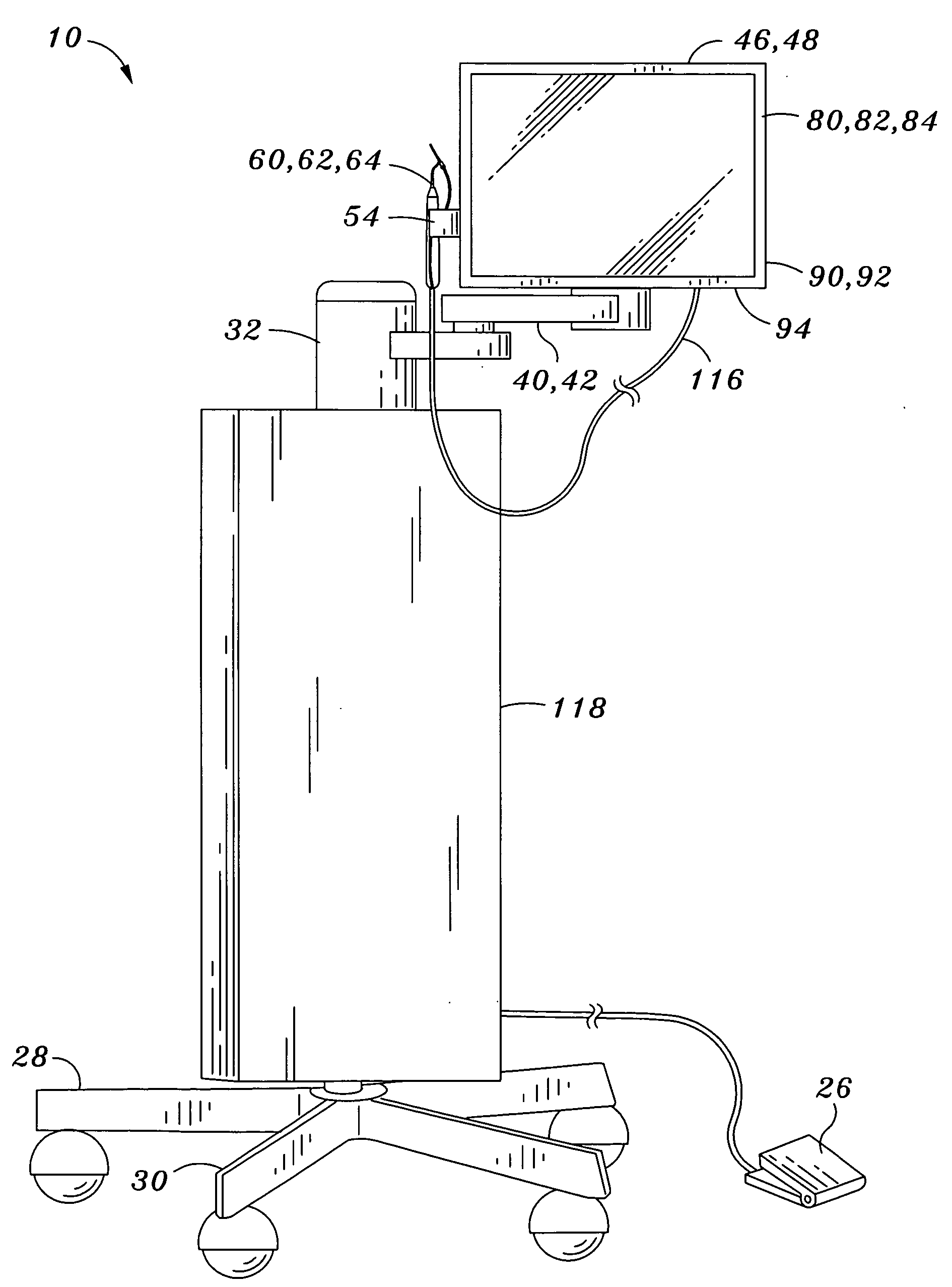
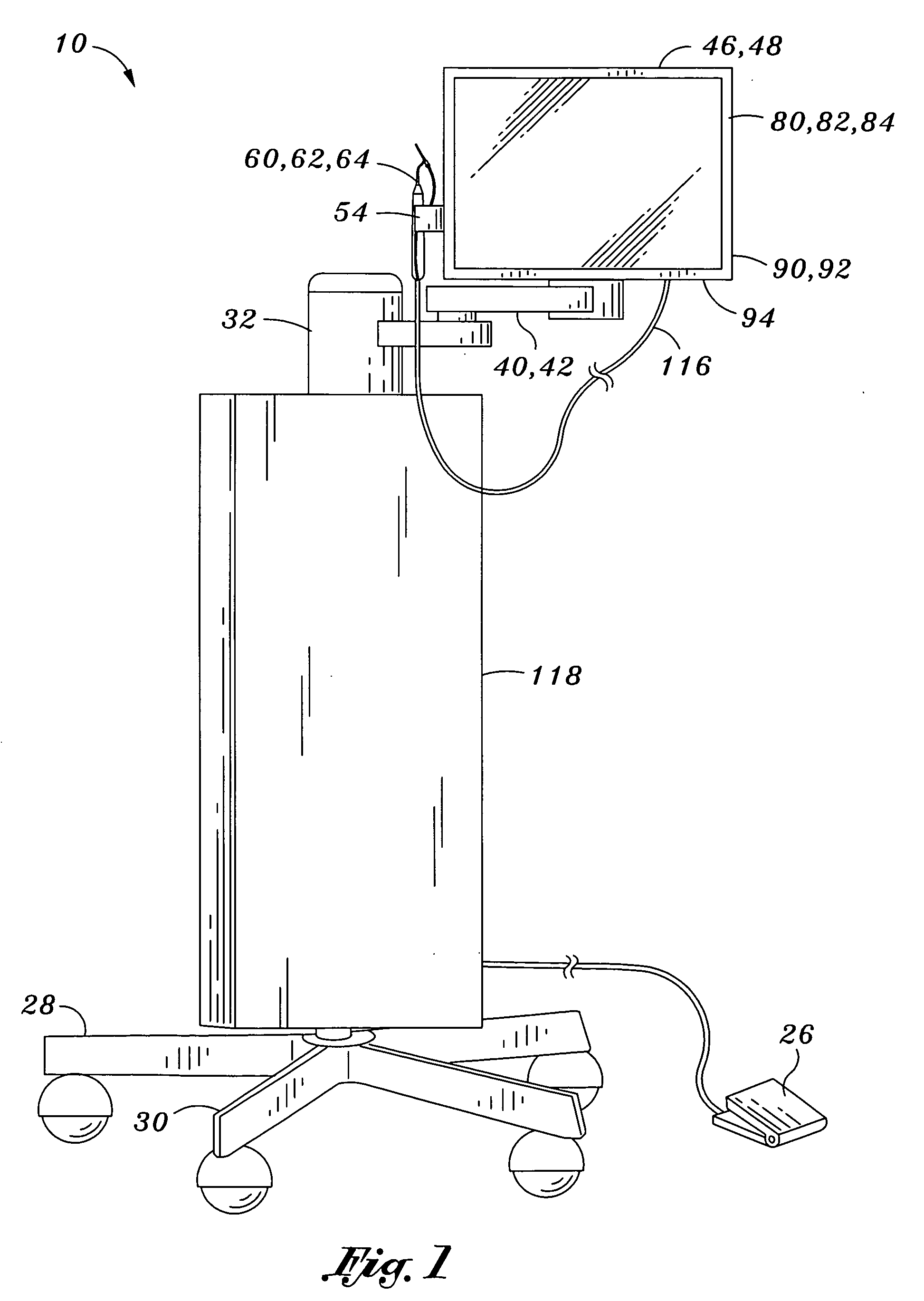
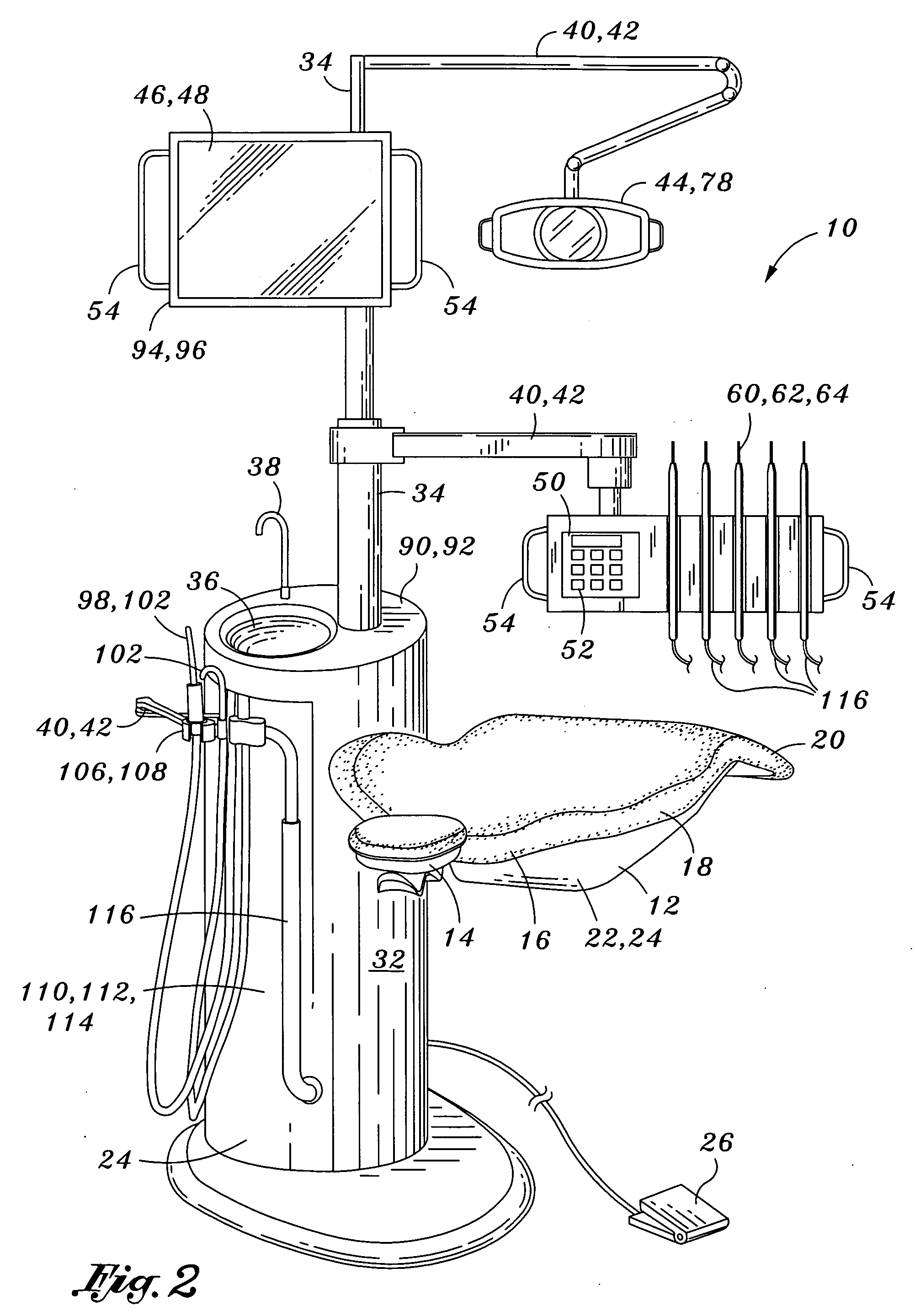
[0032] Shown in FIG. 1 is a dental imaging system 10 which, in its broadest sense, comprises a support frame 28 having an imaging device 60 integrally mounted thereto. As will be described in greater detail below, the imaging device 60 is preferably configured as a perioscopic device which is preferably configured as a fiber-optic based endoscope 62 similar to that shown and described in U.S. Pat. No. 5,230,621 entitled Endoscopic Method and Device for Subgingival Dental Procedures issued to Jacoby, U.S. Pat. No. 5,328,365 entitled System and Method for Endoscopic Subgingival Dental Procedures issued to Jacoby, U.S. Pat. No. 5,347,990 entitled Endoscope with Sterile Sleeve issued to Ebling, U.S. Pat. No. 5,569,161 entitled Endoscopic Sterile Sl...


PUM


Abstract

Provided is a dental imaging system comprising a support frame, an imaging device and a display device. The support frame may include an upright portion mounted upon a base portion which may be portably or stationarily mounted. The imaging device is integrally mounted to the support frame as is the display device. The display device is conductively connected to the imaging device and is preferably configured to display images produced by the imaging device. The dental imaging system is adapted for endoscopic viewing of subgingival anatomy in a unitary structure to minimize space limitations of dental facilities.

Description

CROSS-REFERENCE TO RELATED APPLICATIONS [0001] This application claims priority to pending U.S. Provisional Patent Application No. 60 / 605,011 entitled DENTAL IMAGING SYSTEM AND METHOD OF USE filed on Aug. 27, 2004, the entire contents of which is incorporated by reference herein.STATEMENT RE: FEDERALLY SPONSORED RESEARCH / DEVELOPMENT [0002] (Not Applicable) BACKGROUND OF THE INVENTION [0003] The present invention relates generally to dental equipment and, more particularly, to an integrated dental imaging system that combines a support frame with an instrument console for supporting various dental handpieces such as a perioscope, a display device as well as other diagnostic and treatment devices. The perioscopic device is specifically adapted for permitting visualization, guidance, monitoring and / or assessment of different types of treatment procedure directed to subgingival tooth surfaces or perodontium. [0004] Furthermore, the invention applies fiber optic-based endoscopy technolog...

Claims


Application Information

Patent Timeline
IPC IPC(8): A61C1/00A61C3/00
CPCA61G15/16
Inventor BERGLER, HANS JORGSATHER, KEITH ALLAN
Owner DENTALVIEW
Why Eureka
Try Eureka