Floor cleaning machine using microfiber pad

a floor cleaning machine and microfiber pad technology, applied in carpet cleaning, cleaning filter means, cleaning equipment, etc., can solve the problems of large volume of solution, large consumption of time, and high cost of automatic floor cleaning machines, and achieve the effect of a large machine in one embodimen

Inactive Publication Date: 2006-03-09
MINUTEMAN INT
View PDF3 Cites 27 Cited by
  • Summary
  • Abstract
  • Description
  • Claims
  • Application Information

AI Technical Summary

Benefits of technology

[0020] Persons in the cleaning business will immediately appreciate some of the advantages of the present invention. First, a single pass of a machine removes all loose dirt and debris. Secondly, in the same pass, a cleaning element scrubs the floor clean and leaves little residual water after operation. The size of the machine in one embodiment may thus be reduced for a given application area because there is no need to store recovery solution, or, conversely, the design application area for a given machine may be increased because of the size constraints discussed above. Third, the machine may be simple and inexpensive. No adjustments are necessary during operation. In fact, it is desirable not to leave the operator with the ability to control the amount of solution applied to the microfiber element. The machine uses simple principles familiar to operators of cleaning machines, namely, a vacuum recovery head with a vacuum bag or other filtering system, a conventional vacuum motor, and an air diffusion device for returning the suction air back to the floor behind the microfiber pad.
[0021] Leaving the floors virtually dry immediately after the machine passes provides an obvious maintenance and safety feature in that the area may be accessible to consumers or workers immediately after cleaning.

Problems solved by technology

If the area is of substantial size, these two operations, pre-removal of loose material followed by machine scrubbing, may consume considerable time and require the use of a separate pre-removal machine and then application of a scrubbing machine.
Moreover, automatic floor scrubbers are expensive, particularly more current machines such as rider / scrubbers.
Such machines use a considerable amount of solution and may leave a substantial amount of water behind the scrub deck.
For scrubbing machines designed for application to larger areas, the size of the machine may be limited by design constraints such as maneuverability and the need to provide operator visibility of the floor area in front of the machine.
Currently, in the case of battery-operated scrubbing machines, the physical size of a typical battery pack may occupy a substantial portion of the overall machine.
The presence of two separate tanks, one for clean solution and one for spent solution acts as a limitation on the total area the machine may treat before the need to replace the clean solution and discharge the dirty solution.
However, the size of the tanks are restrained because of the overall size limitations on the machine for practical reasons, and the presence of bulky batteries.
Nevertheless, the size of the typical commercial scrubbing machine has limited the area which the machine may clean before returning to the supply closet to discharge the spent solution and to place additional clean solution in the clean solution tank.

Method used


Image

  • Floor cleaning machine using microfiber pad
  • Floor cleaning machine using microfiber pad
  • Floor cleaning machine using microfiber pad

Examples


Embodiment Construction

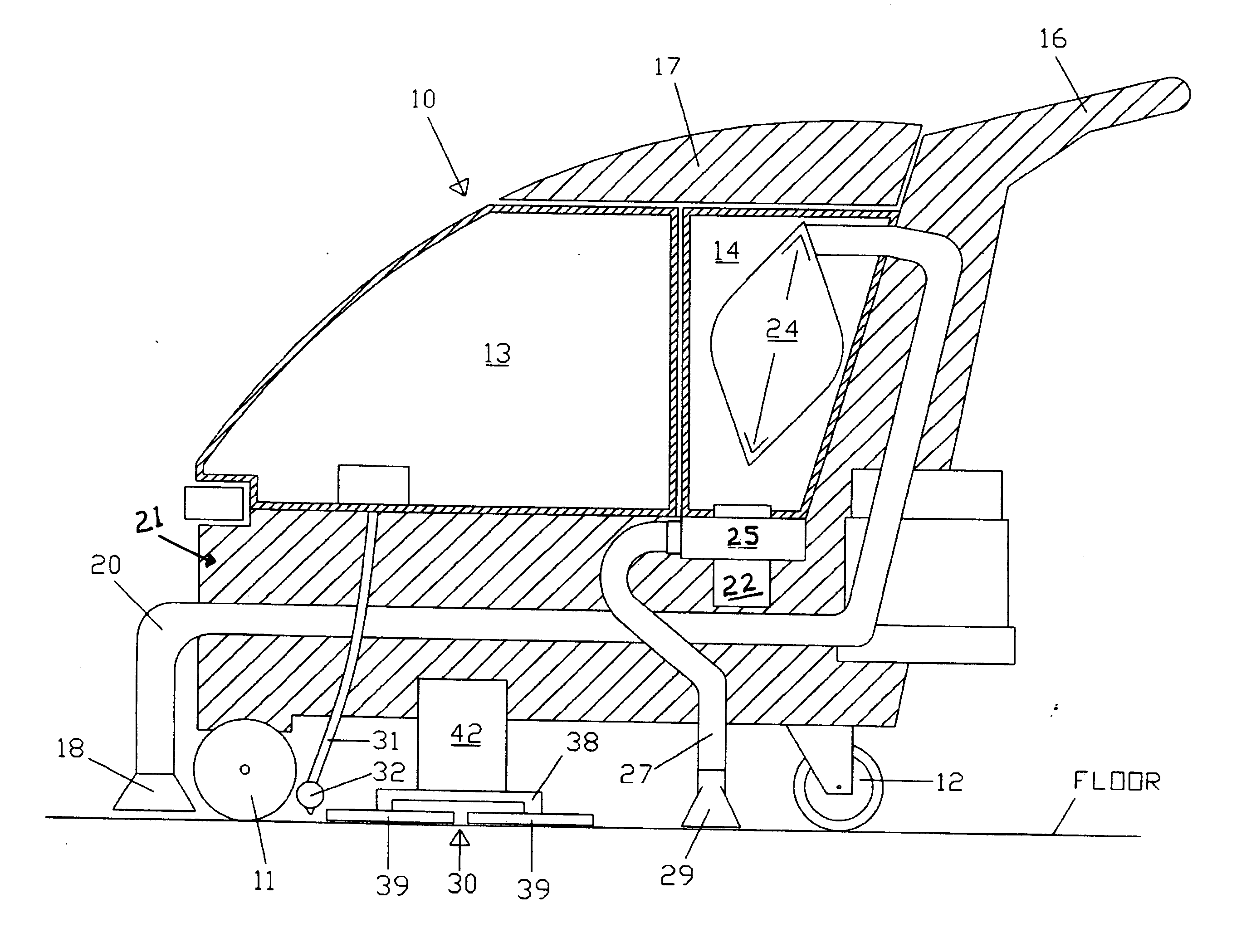
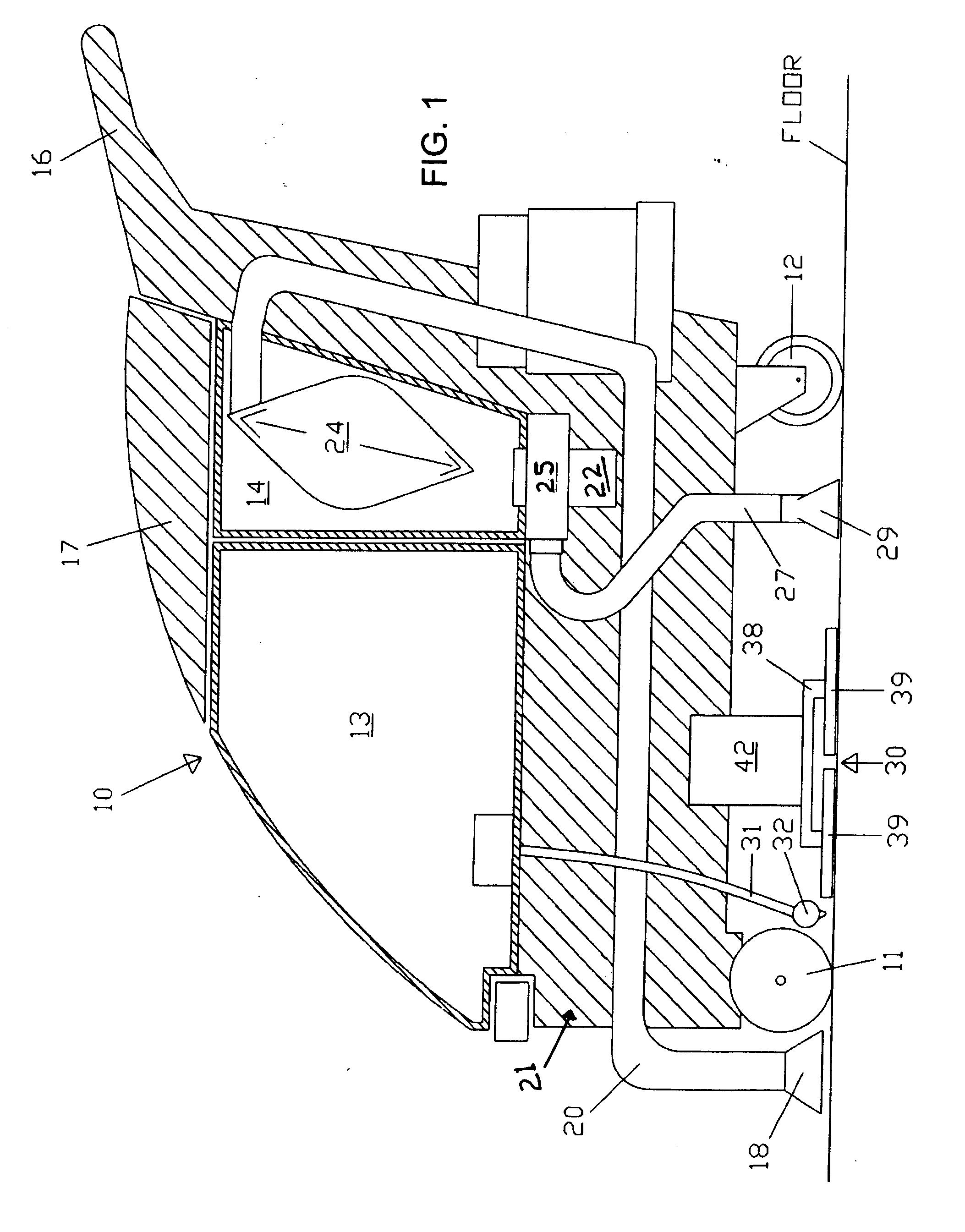
[0029] Referring first to FIG. 1, reference numeral 10 generally designates a floor cleaning machine using a microfiber cleaning element in the form of a pad. Machine 10 includes a pair of front support wheels, the left one of which is designated 11, and a pair of rear caster wheels, the left one of which is seen in FIG. 1 and designated 12. In smaller machines, the machine is designed to be pushed with the rear wheels being caster wheels, but in larger machines, the front or rear wheels may be traction driven, if desired.

[0030] The machine 10 includes a solution tank 13 and a waste tank 14 located behind the solution tank 13. The operator stands to the right of the machine as shown (that is, to the rear of the machine), where he has access to controls on a control panel 15, and controls the machine using a handle 16.

[0031] At the front of the machine, adjacent the floor, there is a vacuum pick-up nozzle 18 which is coupled to the waste tank or suction housing 14 by means of a con...


PUM


Abstract

A cleaning machine for floors and carpets includes a vacuum pick-up in front of the machine for suctioning loose material and debris off the floor. A microfiber cleaning assembly is mounted beneath the machine for cleaning the floor following the vacuum pick-up. The microfiber cleaning element may be motor driven. A source of solution delivers a controlled amount of solution or water to moisten the microfiber cloth. A vacuum motor provides suction to the forward vacuum pick-up, routes the suctioned air through a filter, and the filtered air is then delivered to an air diffuser to dry any residual moisture behind the microfiber cleaning assembly. The microfiber cleaning assembly may have two offset pads driven by a reciprocating or oscillating drive, or one or two cylindrical rollers for receiving and securing the microfiber fabric in the form of a sleeve.

Description

RELATED APPLICATION [0001] This application claims the benefit of U.S. Provisional Application No. 60 / 609,116 filed on Sep. 9, 2004 for “FLOOR CLEANING MACHINE USING MICROFIBER PAD”.FIELD OF THE INVENTION [0002] The present invention relates to hard floor and carpet cleaning machines; and more particularly, it relates to a floor cleaning machine using microfiber cleaning fabric for engaging and scrubbing the floor or other surface to be cleaned. BACKGROUND OF THE INVENTION [0003] One widespread procedure for cleaning floors commercially requires that the floor be pre-swept or vacuumed, normally by hand, prior to using a floor scrubbing or carpet extraction machine to clean the surface. Automatic floor scrubbers and carpet extraction machines typically use a water spray or gravity feed from a solution tank applied directly to the floor (after the loose dirt and debris are removed manually or by a separate vacuum machine), followed by a series of brushes which may include cylindrical ...

Claims


Application Information

Patent Timeline
Patent Type & Authority Applications(United States)
IPC IPC(8): A47L11/30E01H1/08
CPCA47L11/29A47L11/30A47L11/4027A47L11/4088A47L11/4044A47L11/4047A47L11/4069A47L11/4036
Inventor RAU, MICHAEL A.MONDIGO, JESSE V.HOLLY, DAVID R.POLLACK, JEFFREY W.
Owner MINUTEMAN INT
Why Eureka
Try Eureka