Agitator tool

a technology of agitator and tool, which is applied in the field of tools, can solve the problems of blockage of the pump ability, failure of the progressive cavity pump or other failure of the ability to produce fluid, and failure of the conventional pumping means, and achieve the effect of effective agitation of the production fluid, cost-effective production, and energized production fluid

Inactive Publication Date: 2006-03-09
CHARABIN NEIL
View PDF5 Cites 19 Cited by
  • Summary
  • Abstract
  • Description
  • Claims
  • Application Information

AI Technical Summary

Benefits of technology

[0014] An agitator tool in accordance with the present invention, therefore, can create strong turbulent flow to effectively agitate production fluid, keeping debris suspended in the emulsion while breaking out entrained gas, preventing pump intake plugging, agitating the wellbore sump, and keeping the production fluid energized. The agitator tool is cost-effective to produce, adaptable to pumps of different sizes, is easily installed, can be removed with the rod string due to bristle flexibility, and can have substantial bristle outer diameter (OD) due again to flexibility of the bristles.

Problems solved by technology

However, where debris or other particulate matter are present in the production fluid, conventional pumping means can experience failure.
For example, production fluids may contain “sand slugs” which can be sucked into a pump mechanism intake and either cause “sanding” of the pump, requiring costly servicing, or plugging of the intake which results in hysteresis in progressive cavity pumps or other failures in the ability to produce fluids.
Also, gas lock can occur with progressive cavity (PC) pumps where entrained gas passes into the pump mechanism, comes out of solution and accumulates in the cavities; such gas lock may block the ability of the pump to pass fluids through the pump.
As production fluid may comprise a combination of oil, water, gas, sand and other particulates, these problems are of significant concern to companies involved in hydrocarbon production, as the problems can result in costly servicing and pump damage, not to mention the loss of operation efficiency and actual production.
It has been found that only limited agitation is generated, and the entire pump must be pulled if the agitator experiences wear.
Also, the drive spear fastened to the rotor has been found to break in some instances, possibly due to the rotor eccentricity and oscillation, and the Gizmo™ itself can break off of the pump, requiring “fishing” efforts to remove any broken parts.

Method used


Image

  • Agitator tool
  • Agitator tool
  • Agitator tool

Examples


Embodiment Construction

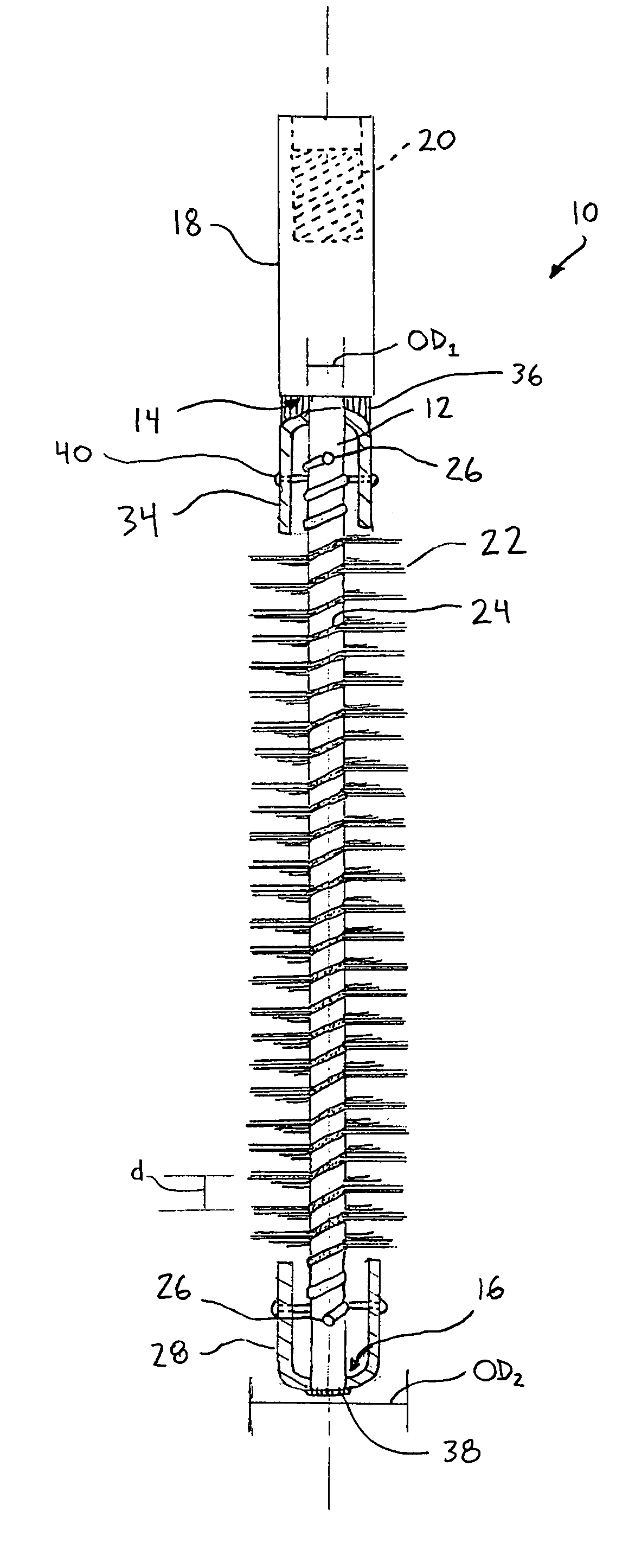
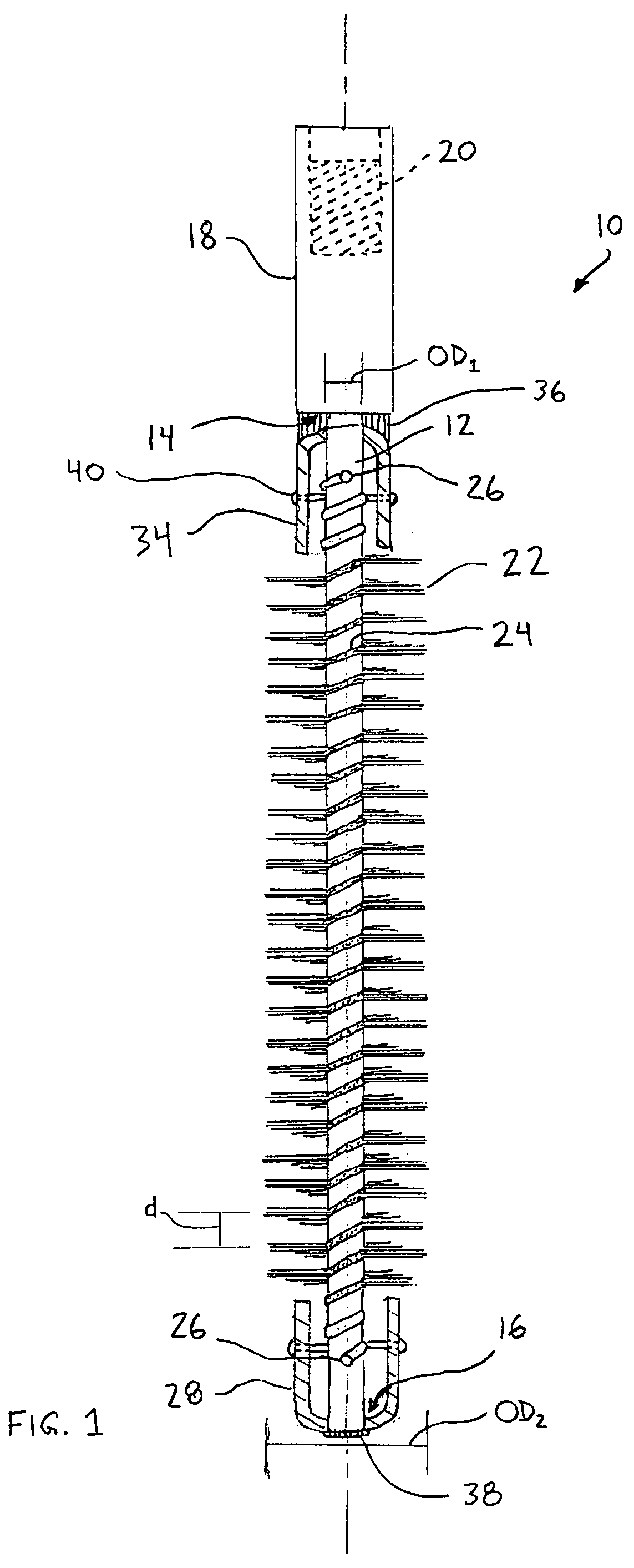
[0019] Referring now in detail to the accompanying drawings, there is illustrated an exemplary embodiment of the agitator tool according to the present invention, generally referred to by the numeral 10. The agitator tool 10, for use in surface flowlines or downhole casings (not shown), comprises an elongate shaft 12 having a downstream end 14 and an upstream end 16. The elongate shaft 12 is a 16″ 4140 steel shaft having an outer diameter OD1 of ½″. The length of the elongate shaft 12 depends on how much sump is required or desired in a given context, and the outer diameter OD1 and shaft geometry (for example, having a bend in the elongate shaft 12, or some other irregular form) can also be adjusted to address specific needs (the outer diameter OD1 will depend to a large degree on the stator / rotor dimensions). Other materials can also be used to manufacture the elongate shaft 12. The elongate shaft 12 is welded to a slim-hole coupling 18 at the downstream end 14, the slim-hole coupl...


PUM


Abstract

A rotatable agitator tool is disclosed for use with a pump mechanism, for agitating production fluid comprising sand or other debris and for breaking out solution gas, comprising an elongate shaft connected to a rotating element such as a rotor, and a plurality of agitation members extending outwardly from the elongate shaft, the agitator tool extending in an upstream direction from the pump mechanism. The agitation members are preferably flexible to allow the agitator tool to be pushed and pulled through a stator (where employed with a progressive cavity pump) without damaging the elastomeric coating on the stator.

Description

FIELD OF THE INVENTION [0001] The present invention relates to tools for use with hydrocarbon or water production, and more particularly to tools that are employed with pumping mechanisms. BACKGROUND OF THE INVENTION [0002] In the context of hydrocarbon or water production, conventional pumping means are of great utility where the production fluid is relatively clean and free of debris or other particulate matter. However, where debris or other particulate matter are present in the production fluid, conventional pumping means can experience failure. For example, production fluids may contain “sand slugs” which can be sucked into a pump mechanism intake and either cause “sanding” of the pump, requiring costly servicing, or plugging of the intake which results in hysteresis in progressive cavity pumps or other failures in the ability to produce fluids. [0003] Also, gas lock can occur with progressive cavity (PC) pumps where entrained gas passes into the pump mechanism, comes out of so...

Claims


Application Information

Patent Timeline
Patent Type & Authority Applications(United States)
IPC IPC(8): E21B17/10E21B28/00
CPCE21B43/128E21B37/00E21B43/38
Inventor CHARABIN, NEIL
Owner CHARABIN NEIL
Why Eureka
Try Eureka