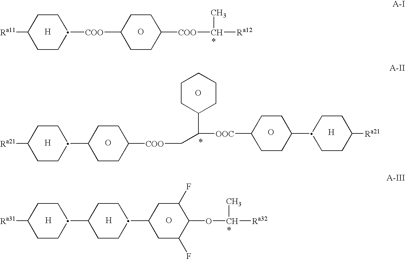
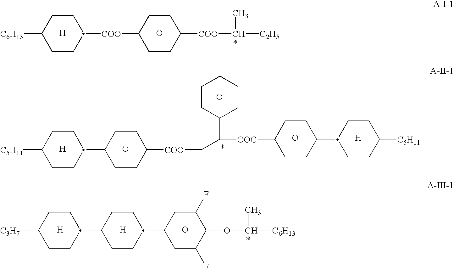
Electrooptical light modulating element, electrooptical display and modulating medium

a light modulating element and light modulating technology, applied in the field of light modulation elements, can solve the problems of clear pronounced viewing angle dependence of contrast, long response time of all conventional displays, and insufficient response time, and achieve the effect of reducing temperature dependence of characteristic voltages

Inactive Publication Date: 2006-03-09
MERCK PATENT GMBH
View PDF7 Cites 58 Cited by
  • Summary
  • Abstract
  • Description
  • Claims
  • Application Information

AI Technical Summary

Benefits of technology

[0017] Surprisingly, it has been found that, as described below, light modulation elements which, like the light modulation elements described in the unpublished application DE 10217273.0, use modulation media in an optically isotropic phase can be significantly improved by using modulation media which are in the blue phase. In particular, light modulation elements having significantly reduced temperature dependence of the characteristic voltages and thus of the operating voltage can thus be achieved.

Problems solved by technology

All conventional displays have relatively long response times, in particular the response times are often not sufficiently short for TV and multimedia applications, which are becoming ever more widespread.
A further disadvantage of the known electro-optical effects employed in liquid-crystal displays is the viewing-angle dependence of the contrast achieved, which is clearly pronounced in most types.
However, the driving voltages are too high for many applications.
However, these electrode structures require considerably more work during production of the light modulation elements.
For the light modulation elements used in practical displays, this temperature dependence of the electro-optical effect is usually too great.
The alternative development of electronic following of the driving voltage is relatively complex.
On the one hand, it generally results in loss of part of the available driving voltage, since this must after all still be sufficiently large even at the highest operating temperature.
The further alternative of keeping the temperature of the light modulation elements constant likewise cannot be achieved easily.
Then, however, the temperature dependence of the operating voltage increases, which is generally undesired.
In this case, the use of a separate black mask may be superfluous.

Method used


Image

  • Electrooptical light modulating element, electrooptical display and modulating medium
  • Electrooptical light modulating element, electrooptical display and modulating medium
  • Electrooptical light modulating element, electrooptical display and modulating medium

Examples


example 1

[0292] A mixture comprising 97% of the achiral liquid-crystal mixture AM-1 of Comparative Example 1a and 3% of the chiral compound B(OC)2C*H-C-3 is prepared and investigated. The chiral compound in the form used has an HTP at 20° C. of +137 μm−1 (in MLC-6828) and +104 μm−1 in MLC-6260.

CompositionConc. / Compound #Abbreviation% by weight1B(OC)2C*H-C-33.02UZU-3A-N7.253GZU-3A-N14.554GZU-4A-N14.555GZU-4O-N14.556PU-3-AN9.77PTU-4O-N14.558CUZU-2-N14.559CUZU-3-N7.25Σ100.0Physical propertiesTchar. =11.5° C.εav.(Tchar. + 6°) =69.9V70(Tchar. + 0.5°) =23 VdV70(Tchar. + 0.5°) / dT =2 V / °dV*70( / V70) / dT =9% / °V70(Tchar. + 2°) =40 VdV70(Tchar. + 2°) / dT =20 V / °dV*70( / V70) / dT =45% / °V70(Tchar. + 2.2°) =42 V

[0293] The mixture has a blue phase over a range of about 2 degrees with the following phase sequence: N* 11.5° C. BP 13.5° C. I.

[0294] The mixture is, as described in Comparative Example 1a, introduced into a test cell and investigated as described. In particular, its electro-optical properties are i...

example 2a

[0307] A mixture comprising 90% of the achiral liquid-crystal mixture AM-2 of Comparative Example 2 and 10% of the chiral compound B(OC)2C*H-C-3 is prepared and investigated. This mixture had a characteristic temperature of 22.5° C., but 24.4° C. in the cell, which is assumed here to be the characteristic temperature. The temperature dependence of the voltage V70 is shown in the following table (Table 3).

TABLE 3Temperature dependence of the characteristic voltages ofExample 2a#T / ° C.V70 / V1−19.31562−17.31163−15.5934−13.5825−11.6806−9.6827−7.7888−5.6949−3.710210−1.9108112.0125125.9143139.7164

[0308] As can be seen from this table (Table 3), the characteristic voltage V70 of the cell containing this doped mixture does not increase with increasing temperature, as in Comparative Example 1a and Example 1, but instead initially decreases with increasing temperature, then passes through a minimum at about −11.6° C. and only then rises again with further increasing temperature. The temperat...

example 2b

[0311] 85% of the achiral liquid-crystal mixture AM-2 of Example 1 was with 15% of the dopant mixture DM-1 having the following composition.

Composition DM-1Conc. / HTP (MLC-HTPCompound% by6828) / (MLC-6260) / #Abbreviationweightμm−1μm−11B(OC)2C*H-C-328.6+137 +1042(6OPZ)2X*14.2+58n.d.3(1OPZPZ)2X*14.3+80n.d.4SS-(5CPZ)2BE14.2−56n.d.5RR-(5CPZ)2BE14.3+56n.d.6R-101114.4n.d. +27Σ100.0

Notes:

see Table 1

[0312] The chiral compounds used in the dopant mixture DM-1 all, apart from one exception, have a high, positive value of the HTP in the reference mixture having the stated composition.

[0313] For the resultant modulation medium, it was not possible to determine a clearing point or a transition into the blue phase under the microscope at temperatures down to −20° C. The mixture comprising 85% of AM-2 and 15% of DM-1 is mixed with 0.1% of the phenol of the formula

[0314] introduced into a test cell and investigated as described in Comparative Example 1a. In particular, its electro-optical proper...


PUM

PropertyMeasurementUnit
temperatureaaaaaaaaaa
clearing pointaaaaaaaaaa

Abstract

The invention relates to electrooptical light modulating elements, to electrooptical displays containing elements of this type, and to display systems, e.g. television screens and computer monitors, and to the modulating media used therein. The inventive light modulating elements contain a mesogenic modulating medium that exists in an optically isotropic phase when the light modulating elements are in operation and, in addition to having a good contrast, a low dependency on the viewing angle and very short switching times, they are particularly characterized by having relatively low driving voltages with a very low dependency on temperature. The inventive modulating media are characterized in that they contain a chiral constituent. They preferably also contain an achiral constituent. Especially preferred, the control media comprise a blue phase.

Description

FIELD OF THE INVENTION [0001] The present invention relates to light modulation elements, to displays containing same, and to light modulation media. The light modulation elements preferably use modulation media which have anisotropic properties at certain temperatures, such as, for example, liquid crystals. The light modulation elements are operated at a temperature at which the modulation media are in the blue phase. Similar displays which use modulation media which are in the isotropic phase are described in DE 102 17 273.0 and in the hitherto unpublished patent applications DE 102 41 301.0 of 04.09.2002, two further applications by the applicant of the present application. [0002] The present invention relates to an electro-optical light modulation element and to electro-optical displays and display systems containing elements of this type, such as, for example, television screens and computer monitors, and to the modulation media used in the light modulation elements. The light ...

Claims


Application Information

Patent Timeline
Patent Type & Authority Applications(United States)
IPC IPC(8): G02F1/03G02F1/07C09K19/02C09K19/46C09K19/58G02F1/137
CPCC09K19/0275C09K19/46C09K19/586G02F2001/13793G02F1/07G02F1/13718C09K19/588C09K2019/0444G02F1/13793G02F1/13
Inventor HECKMEIER, MICHAELCZANTA, MARKUSGOETZ, ACHIMKIRSCH, PEERFARRAND, LOUISETAUGERBECK, ANDREASMONTENEGRO, ELVIRA
Owner MERCK PATENT GMBH
Why Eureka
Try Eureka