Fuel cell, electrode for fuel cell, and method producing them

a fuel cell and electrode technology, applied in the field of fuel cells, can solve the problems of unsolved problems such as the energy density of a lithium ion cell now almost reaching an upper theoretical limit, the increase in the power consumption of an electronic device, and the reduction of the output power of the fuel cell. achieve the effects of simple manufacturing steps, high power, and light weigh

Inactive Publication Date: 2006-03-09
NEC CORP
View PDF3 Cites 19 Cited by
  • Summary
  • Abstract
  • Description
  • Claims
  • Application Information

AI Technical Summary

Benefits of technology

[0031] By bonding a substrate and a current-collector to each other, adhesion between the substrate and the current-collector is kept high, ensuring electrical connection of the substrate and the current-collector to each other. Hence, the electrode used for a fuel cell, in accordance with the present invention makes it no longer necessary to use parts which were necessary for coupling a substrate and a current-collector to each other, such as an end plate and a bolt and a nut, but which prevented a fuel cell from being fabricated small. Thus, the fuel cell in accordance with the present invention can be fabricated thin, small, and light-weighted.
[0090] Since the method of fabricating a fuel cell, in accordance with the present invention includes the step of fabricating the electrode in accordance with the present invention, the method naturally includes the step of bonding the substrate and the current-collector in each of the fuel and oxidizer electrodes to each other. Accordingly, it is possible to keep the substrate and the current-collector in close contact with each other without an end plate and a fastener, and hence, there is provided a method of fabricating a fuel cell, which is capable of fabricating a fuel cell which outputs high power, and is thin, small, and light-weighted. In addition, the method of fabricating a fuel cell, in accordance with the present invention simplifies fabrication steps, because the method makes it no longer necessary to carry out a step of fastening a substrate, a current-collector, and a catalyst layer to one another by means of an end plate and the like.

Problems solved by technology

With recent realization of computerized society, an electronic device such as a personal computer has to deal with a significantly increased amount of data, resulting in remarkable increase in power consumption of an electronic device.
However, an energy density of a lithium ion cell now almost reaches an upper theoretical limit.
Thus, the problem of reduction in output power of the fuel cell remains unsolved.
If the parts of the fuel cell do not make close contact with each other, an internal resistance of the fuel cell would be increased, resulting in reduction in output power of the fuel cell.
This results in difficulty in fabricating a fuel cell to be thin and light-weighted.
However, as mentioned earlier, the conventional fuel cell is accompanied with a problem that if fabricated small in size and light in weight, the fuel cell would have an increased internal resistance, and hence, output power of the fuel cell would be reduced.
As mentioned above, the conventional fuel cell is accompanied with a problem that the fuel cell cannot be fabricated thin and light-weighted, because the end plates are arranged to make contact with the fuel and oxidizer electrodes, and the fuel and oxidizer electrodes are caused to make sufficient close contact with each other through a fastener such as a bolt and a nut.
The conventional fuel cell is accompanied further with a problem that if the conventional fuel cell is fabricated thin and light-weighted by thinning the end plates, the parts constituting the fuel cell cannot make close contact with one another, resulting in an increase in an internal resistance and reduction in output power.
In particular, the conventional fuel cell is accompanied with a problem that an increase in output power is not compatible with fabrication of the fuel cell to be thin, small and light-weighted for the purpose of application to a mobile device.

Method used


Image

  • Fuel cell, electrode for fuel cell, and method producing them
  • Fuel cell, electrode for fuel cell, and method producing them
  • Fuel cell, electrode for fuel cell, and method producing them

Examples


first embodiment

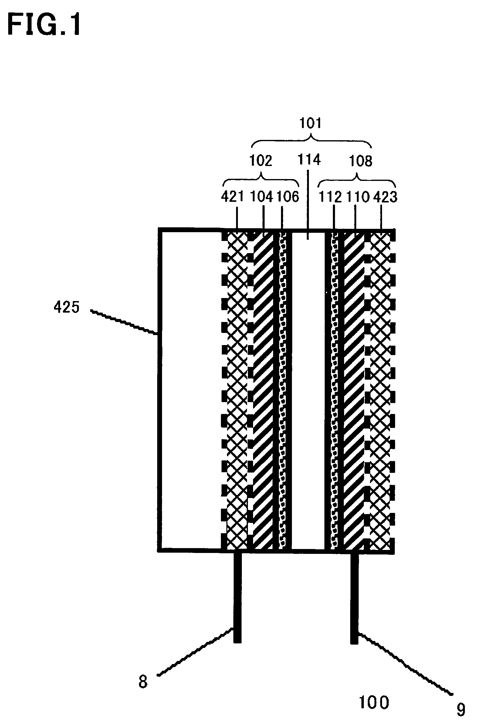
[0114]FIG. 1 is a schematic cross-sectional view of a unit cell 101 in a fuel cell 100 in accordance with the first embodiment of the present invention.

[0115] Though the fuel cell 100 in accordance with the first embodiment includes the single unit cell 101, the fuel cell 100 may be designed to include a plurality of the unit cells 101.

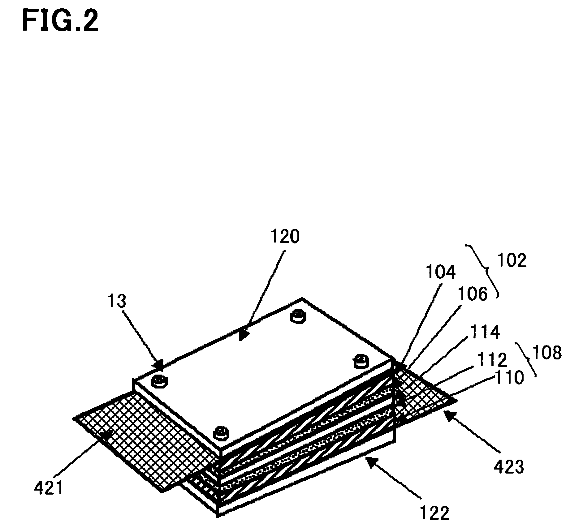
[0116] As illustrated in FIG. 1, the unit cell 101 is comprised of a fuel electrode 102, an oxidizer electrode 108, and a solid electrolyte film 114 sandwiched between the fuel electrode 102 and the oxidizer electrode 108 (a pair of the fuel electrode 102 and the oxidizer electrode 108 is called “catalyst electrodes”).

[0117] The fuel electrode 102 is comprised of a substrate 104, a catalyst layer 106 arranged on one of surfaces of the substrate 104, and a current-collector 421 arranged on the other surface of the substrate 104. The oxidizer electrode 108 is comprised of a substrate 110, a catalyst layer 112 arranged on one of surfaces of the substr...

second embodiment

[0188] A single fuel cell can be fabricated by electrically connecting a plurality of the fuel cells 100 as unit cells to one another.

[0189] An example of such a single fuel cell is illustrated in FIG. 3.

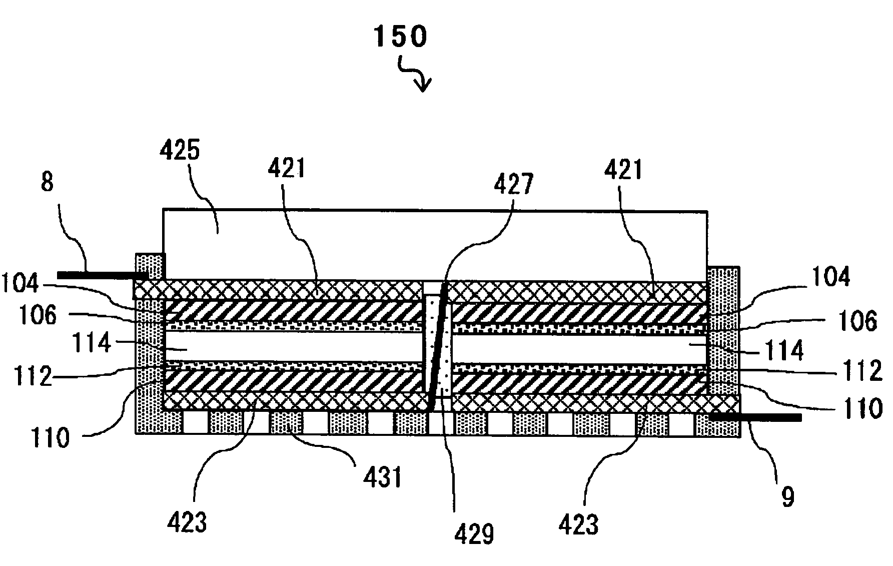
[0190] A fuel cell 150 illustrated in FIG. 3 is comprised of two unit cells each comprised of the fuel cell 100 in accordance with the first embodiment, electrically connected in series to each other. The two unit cells are electrically connected to each other such that the current-collector 421 of one of the unit cells is electrically connected to the current-collector 423 of the other unit cell through a connection electrode 427. The connection electrode 427 is sealed with a seal 429 composed of electrically insulating material.

[0191] The two unit cells commonly have a single fuel reservoir 425. The two unit cells are packed with a package 431. Output terminals 8 and 9 extend from the current-collectors 421 and 423 which are not electrically connected to the connection electrod...

third embodiment

[0195] Another example of a fuel cell comprised of a plurality of unit cells each comprised of the fuel cell 100 in accordance with the first embodiment, electrically connected to one another is illustrated in FIG. 4 as the third embodiment.

[0196] Whereas each of the unit cells 100 in the fuel cell 150 illustrated in FIG. 3 is designed to individually have the solid electrolyte film 114, the two unit cells 100 defining the fuel cell 160 in accordance with the third embodiment, illustrated in FIG. 4, are designed to commonly have a single solid electrolyte film 114. The fuel cell 160 in accordance with the third embodiment has the same structure as that of the fuel cell 150 illustrated in FIG. 3 except the common singe solid electrolyte film 114.

[0197] Since the fuel cell 160 in accordance with the third embodiment is comprised of the unit cells, that is, the fuel cells 100 in accordance with the first embodiment, the fuel cell 160 has the advantages provided by the fuel cell 100 i...


PUM

PropertyMeasurementUnit
thicknessaaaaaaaaaa
thicknessaaaaaaaaaa
voltageaaaaaaaaaa

Abstract

The present invention provides a fuel cell which is small-sized and light-weight for mounting in a mobile device, and has a high output-density. A current-collector 421 of a fuel electrode (or a current-collector 423 of an oxidizer electrode) is bonded to a substrate 104 (or a substrate 110) of a fuel electrode 102 (or an oxidizer electrode 108) in a fuel cell 100, rendering the current-collector 421 (or the current-collector 423) to be thin and light-weight, and making it no longer necessary to use an end plate and a fastener. Fuel or oxidizer is supplied directly to a surface of the current-collector 421 or 423.

Description

FIELD OF THE INVENTION [0001] The invention relates to a fuel cell, an electrode used for a fuel cell, and a method of fabricating them. PRIOR ART [0002] With recent realization of computerized society, an electronic device such as a personal computer has to deal with a significantly increased amount of data, resulting in remarkable increase in power consumption of an electronic device. In particular, a mobile electronic device is now urgently required to have a countermeasure to an increase in power consumption caused by an increase in capacity for dealing with data. [0003] A mobile electronic device is currently generally designed to have a lithium ion cell as a power source. However, an energy density of a lithium ion cell now almost reaches an upper theoretical limit. Hence, in order to prolong a duration for continuously use a mobile electronic device, it was necessary to lower a frequency at which a central processing unit (CPU) is driven for reducing power consumption. [0004]...

Claims


Application Information

Patent Timeline
Patent Type & Authority Applications(United States)
IPC IPC(8): H01M4/86H01M4/90H01M4/92H01M8/10B05D5/12H01M4/88H01M4/96H01M8/02
CPCH01M4/8605H01M4/8807H01M8/0202H01M8/0232Y02E60/521H01M8/0247H01M8/0297H01M8/1004H01M8/0234Y02E60/50Y02P70/50H01M8/0258H01M8/0271H01M8/241H01M8/2457
Inventor YOSHITAKE, TSUTOMUNAKAMURA, SHINKIMURA, HIDEKAZUKUROSHIMA, SADANORISHIMAKAWA, YUICHIMANAKO, TAKASHIIMAI, HIDETOKUBO, YOSHIMI
Owner NEC CORP
Why Eureka
Try Eureka