Wireless protocol converter

a wireless protocol and converter technology, applied in the field of wireless data communication, can solve the problems of increasing the location limitation of cellular broadband wireless technology, reducing the coverage area of broadband wireless service, and reducing the coverage area of conventional cellular telephone technology, so as to achieve the effect of expanding the coverage area of broadband wireless servi

Inactive Publication Date: 2006-03-09
PARKER VISION INC
View PDF15 Cites 102 Cited by
  • Summary
  • Abstract
  • Description
  • Claims
  • Application Information

AI Technical Summary

Benefits of technology

[0014] The devices are able to operate within a range of the repeater station. The present invention thus extends the coverage area of the broadband wireless service to the range of the repeater station.

Problems solved by technology

Conventional cellular telephone systems do not provide uniform indoor or outdoor coverage.
Thus, it is expected that broadband wireless technology, such as cellular broadband wireless technology, will suffer from at least the same and most likely more of the location limitations as conventional cellular telephone technology.
In fact, for a number of reasons, it is expected that cellular broadband wireless technology will suffer even greater location limitations due to factors such as increased bandwidth and additional users.
Cell phone systems deploying higher frequency technology will have increased distance and reliability problems due to increased directionally and free space loss.
In many locations, the current coverage area is unacceptable for low speed voice applications.
As a result, in some environments and locations, reception of broadband wireless communications is expected to be poor or non-existent.
In other words, broadband wireless communications, such as planned internet access through cellular telephone systems, will not provide adequate coverage in many locations and situations.

Method used


Image

  • Wireless protocol converter
  • Wireless protocol converter
  • Wireless protocol converter

Examples


Embodiment Construction

I. Introduction

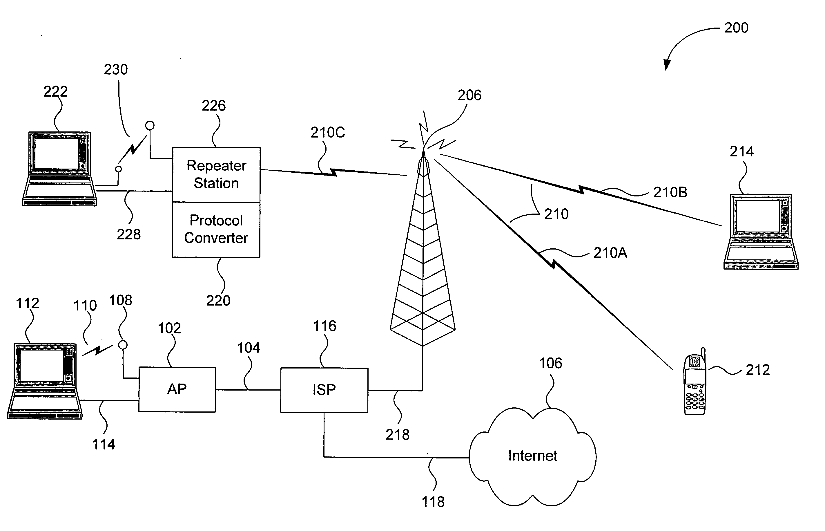
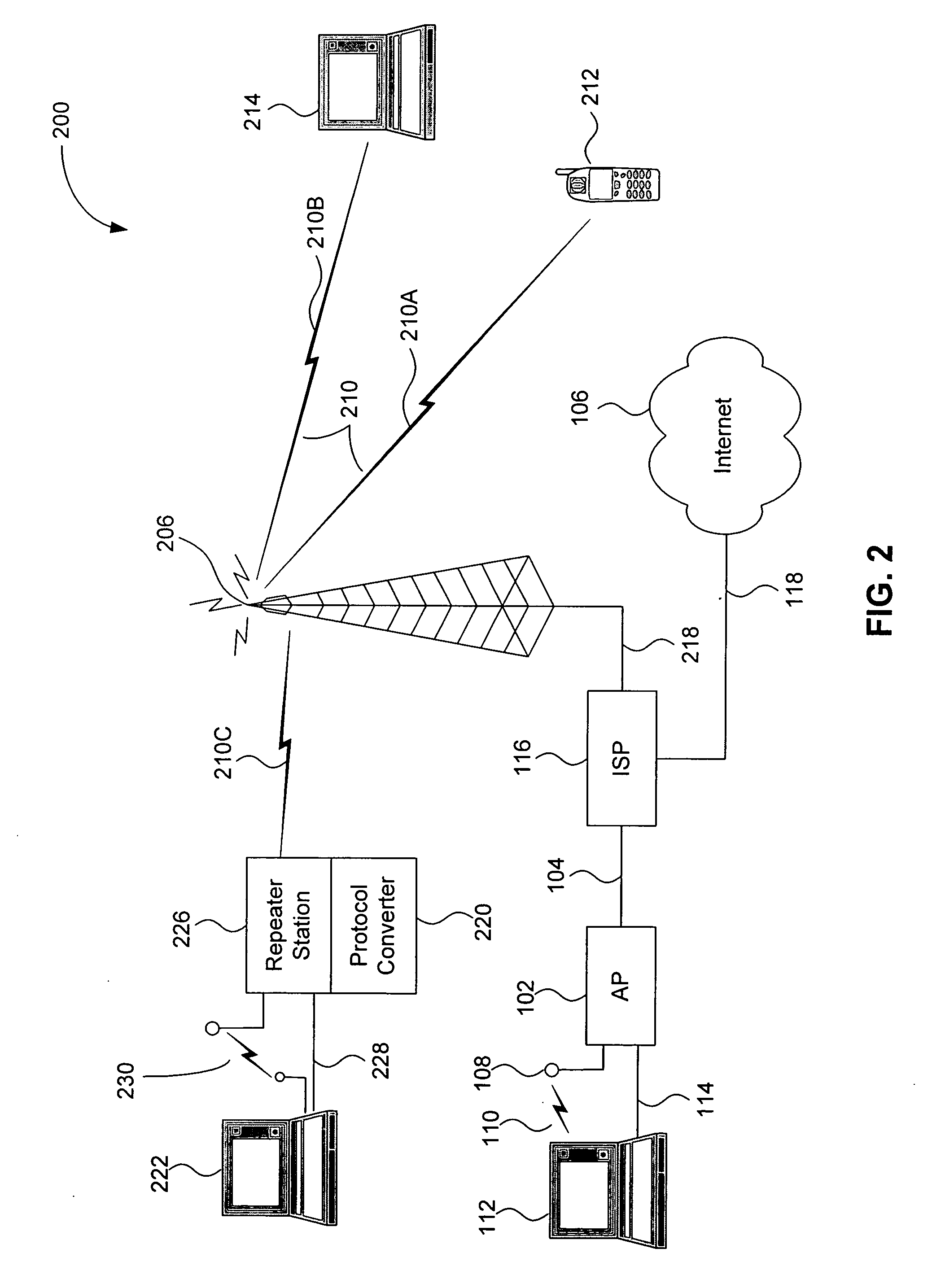
[0021] The present invention is directed to methods and systems for extending the coverage area of broadband wireless communications, such as internet access through cellular telephone systems.

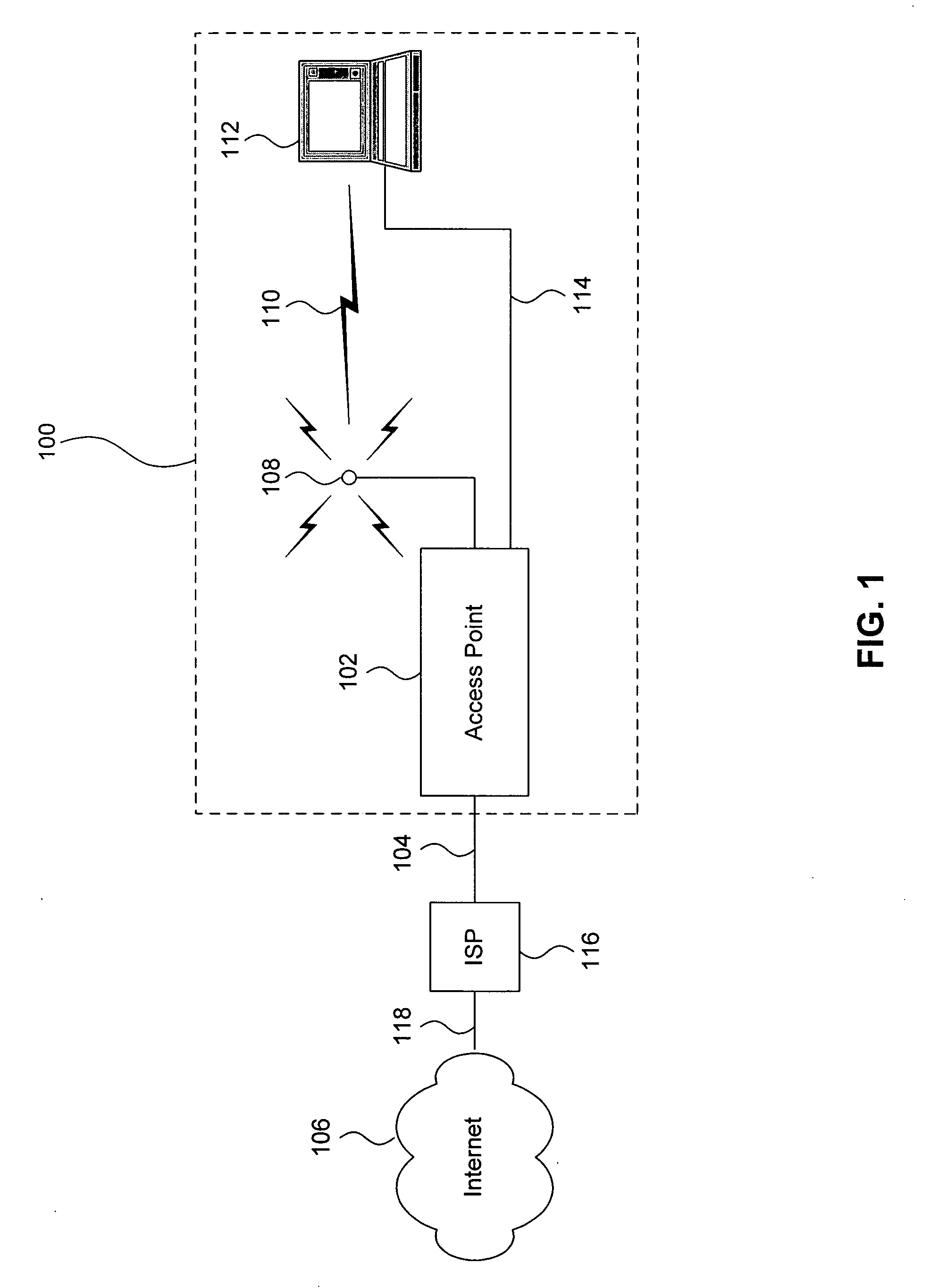
[0022]FIG. 1 is a block diagram of an example local area network (“LAN”) system 100. The LAN system 100 includes an access point (“AP”) 102, such as a wired and / or wireless router. The AP 102 is connected via physical connection 104 to an internet service provider (“ISP”) 116. The physical connection 104 can be, for example, a hardwired broadband connection or a wireless broadband connection. The internet service provider (“ISP”) 116 is connected to the internet 106 through a connection 118.

[0023] The AP 102 interfaces between the ISP 116 and one or more devices 112. The AP 102 optionally includes a wireless router and an antenna 108. In this embodiment, the AP 102 transmits and receives an electromagnetic wave 110 to communicate data with one or more of the devices 112, such ...


PUM


Abstract

Methods and systems for interfacing between broadband wireless communication systems and Local Area Network (LAN) systems includes a repeater station placed at a location that receives sufficient signal strength from a broadband wireless service provider. LAN devices interface with the broadband wireless service provider through the repeater station. The LAN devices are able to operate within the operating range of the repeater station. The repeater station includes a protocol converter that interfaces between a first protocol associated with the broadband wireless service provider, and one or more protocols associated with the devices. For example, and without limitation, the protocol converter converts between a first protocol associated with a Wide Area Network (WAN) service provider, such as a cellular telephone protocol, and one or more LAN protocols associated with the one or more devices. The one or more devices optionally include one or more wireless devices.

Description

BACKGROUND OF THE INVENTION [0001] 1. Field of the Invention [0002] The present invention relates generally to wireless data communication and, more particularly, to broadband wireless data communication. [0003] 2. Related Art [0004] There is an increasing demand for broadband wireless communications, such as wireless internet access, which service providers are attempting to provide. [0005] Cellular telephone companies are advertising future availability of broadband wireless internet access. According to the advertising, users will be able to connect to the internet at ever increasing speeds using cellular telephone systems. [0006] Conventional cellular telephone systems do not provide uniform indoor or outdoor coverage. For example, a cellular telephone may work well in one part of a building but not in another part of the building or in one part of a city, but not the other. [0007] Thus, it is expected that broadband wireless technology, such as cellular broadband wireless techn...

Claims


Application Information

Patent Timeline
Patent Type & Authority Applications(United States)
IPC IPC(8): H04Q7/20H04W16/26H04W76/04H04W88/10H04W92/02H04W92/10
CPCH04L65/1033H04W16/26H04W88/10H04W80/045H04W92/10H04L69/08H04W92/02
Inventor PARKER, JEFFREY L.
Owner PARKER VISION INC
Why Eureka
Try Eureka