Shaft sensorless angular position and velocity estimation for a dynamoelectric machine based on extended rotor flux

a dynamoelectric machine and rotor technology, applied in the direction of speed/acceleration/shock measurement, digital computers, instruments, etc., can solve the problems of direct current drifting and initial value holding problems of pure integrators, and achieve the effect of improving estimation accuracy

Active Publication Date: 2006-03-09
HAMILTON SUNDSTRAND CORP
View PDF1 Cites 25 Cited by
  • Summary
  • Abstract
  • Description
  • Claims
  • Application Information

AI Technical Summary

Benefits of technology

[0005] Ideally, a pure integrator should be used to reconstruct the flux. However, in practice, a pure integrator has direct current (DC) drifting and initial value holding problems. The invention employs a special lag function to approximate the pure integrator. The corner frequency of the lag function can be either fixed or adjusted according to the rotor a

Problems solved by technology

However, in practice, a pure integrator has direct cur

Method used


Image

  • Shaft sensorless angular position and velocity estimation for a dynamoelectric machine based on extended rotor flux
  • Shaft sensorless angular position and velocity estimation for a dynamoelectric machine based on extended rotor flux
  • Shaft sensorless angular position and velocity estimation for a dynamoelectric machine based on extended rotor flux

Examples


Embodiment Construction

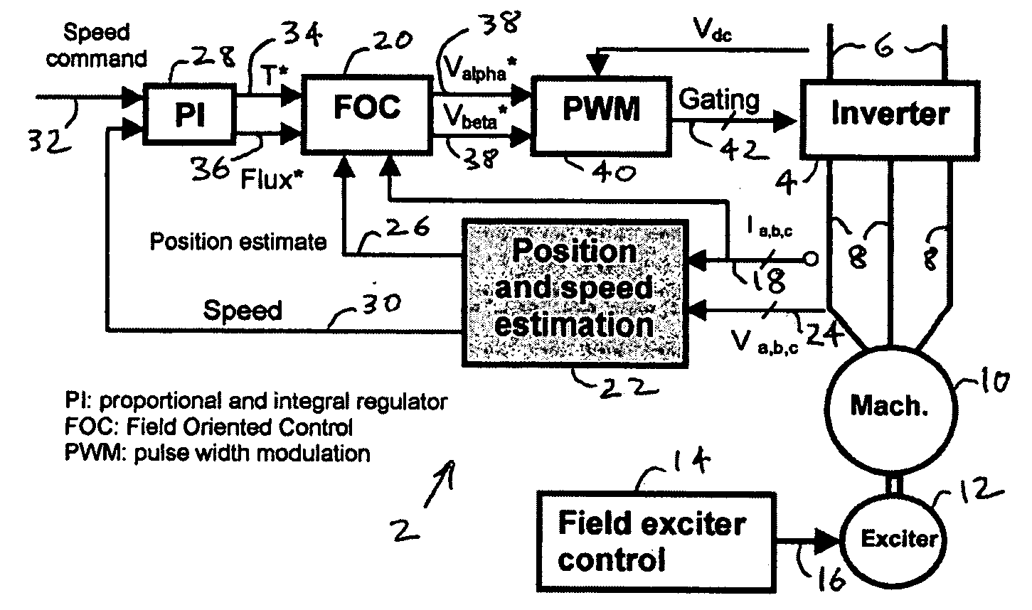
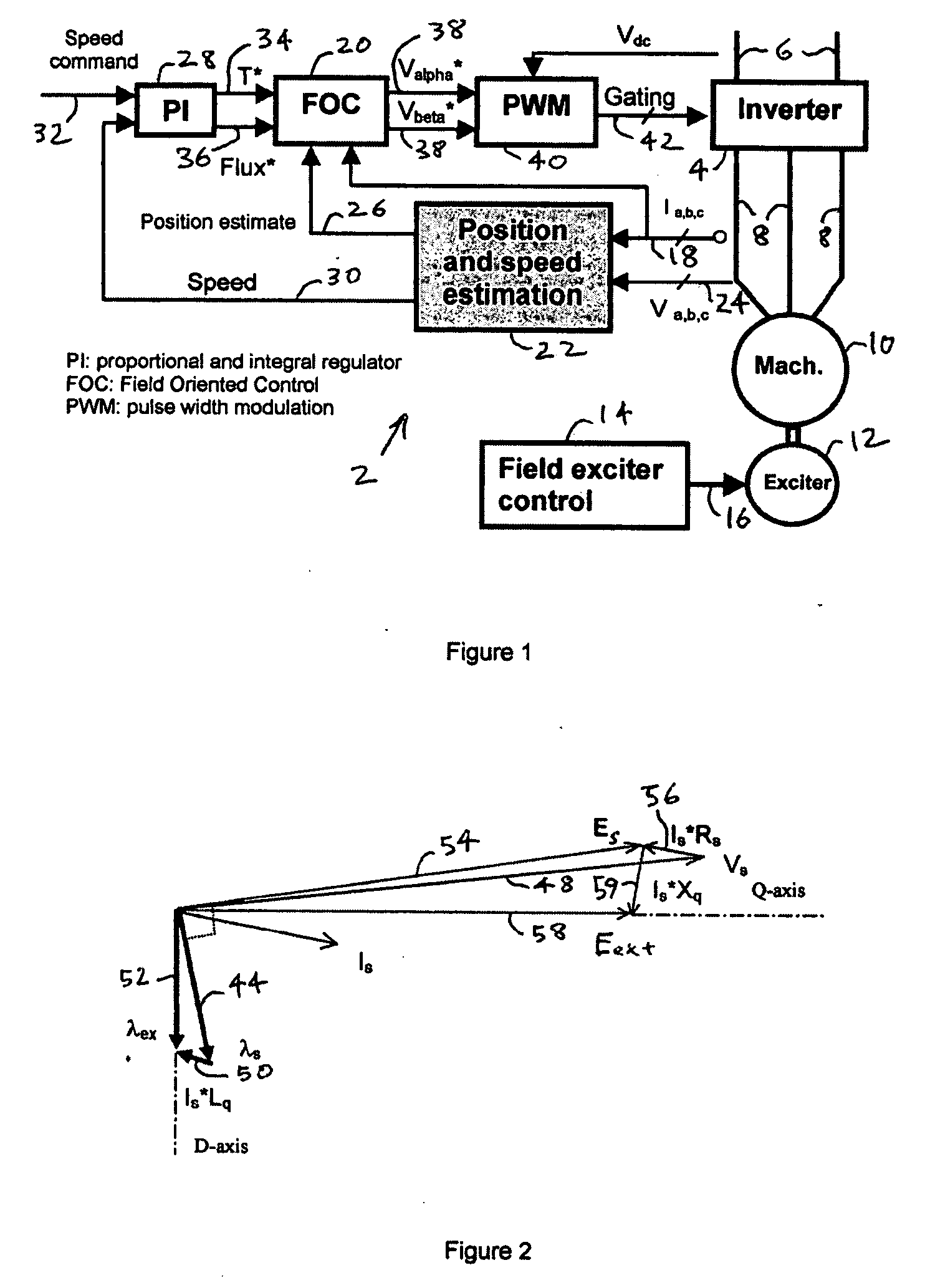
[0018]FIG. 1 shows a high level block diagram of a sensorless rotor angular position and velocity sensing system 2 for a dynamoelectric machine that may incorporate dynamoelectric machine extended flux estimation according to the invention. A power inverter 4 converts direct current (DC) power supplied on lines 6 to polyphase alternating current (AC) power on lines 8 that supply a stator of a dynamoelectric machine 10. Typically, three phase AC power is supplied to the dynamoelectric machine. The dynamoelectric machine 10 has a rotor that may be energised by an exciter 12. The exciter 12 is controlled by a exciter field controller 14 through signal path 16.

[0019] Current level in the lines 8 is measured and a current level signals representative of this level travel down a feedback signal path 18 to a FOC controller 20. An angular position and velocity estimation controller 22 receives both the current level signals on the signal path 18 and potential level signals on a signal path...


PUM


Abstract

A shaft sensorless rotor angular position and velocity sensing system for a dynamoelectric machine that is based on dynamoelectric machine extended flux estimation.

Description

FIELD OF THE INVENTION [0001] The invention relates to rotor angular position and velocity sensing systems for mechanical shaft sensorless control of dynamoelectric machines, and more particularly to an improved system for resolving the position of a rotor for a dynamoelectric machine using an estimate of extended rotor flux. BACKGROUND OF THE INVENTION [0002] A polyphase alternating current (AC) dynamoelectric machine can be used as a motor or a generator. In aeronautical applications, it is desirable to use a single machine for a starter motor and a generator to reduce size and weight. An aircraft generator can be used as a motor to start the propulsion engine for the aircraft when it is powered by an inverter. [0003] To reduce cost and improve reliability, it is very desirable for the engine starter to eliminate mechanical shaft sensor. In general, there are two categories in sensorless motor control, the back EMF based method and the signal injection method. The back EMF based m...

Claims


Application Information

Patent Timeline
IPC IPC(8): G01P3/00G06F15/00
CPCH02P21/06
Inventor HU, JUNROMENESKO, CHARLESMARKUNAS, ALBERT L.
Owner HAMILTON SUNDSTRAND CORP
Why Eureka
Try Eureka