Exhaust system

a technology of exhaust system and exhaust heat, which is applied in the direction of generator/motor, machine/engine, generator/motor, etc., can solve the problems of reducing the thermoelectric unable to effectively collect thermal energy, and reducing the thermal energy conversion efficiency of the exhaust heat power generation apparatus, so as to prevent the degradation of catalysts and improve fuel efficiency

Inactive Publication Date: 2006-03-16
TOYOTA JIDOSHA KK
View PDF9 Cites 37 Cited by
  • Summary
  • Abstract
  • Description
  • Claims
  • Application Information

AI Technical Summary

Benefits of technology

[0009] It is an object of the invention to provide an exhaust system that prevents degradation of the catalyst while improving the fuel efficiency.

Problems solved by technology

The temperature of the exhaust gas passing at the position downstream of the exhaust catalyst, however, becomes low because it has been used for increasing the catalytic temperature or it has been dispersed as it flows, resulting in decrease in the thermal energy.
As a result, the thermoelectric conversion efficiency of the exhaust heat power generation apparatus is decreased, failing to effectively collect the thermal energy.
When the catalytic temperature exceeds the activated temperature, its purification effect is deteriorated, which may thermally degrade the catalyst.
This may increase the fuel supply quantity, resulting in deteriorated fuel efficiency.

Method used


Image

  • Exhaust system
  • Exhaust system
  • Exhaust system

Examples


Embodiment Construction

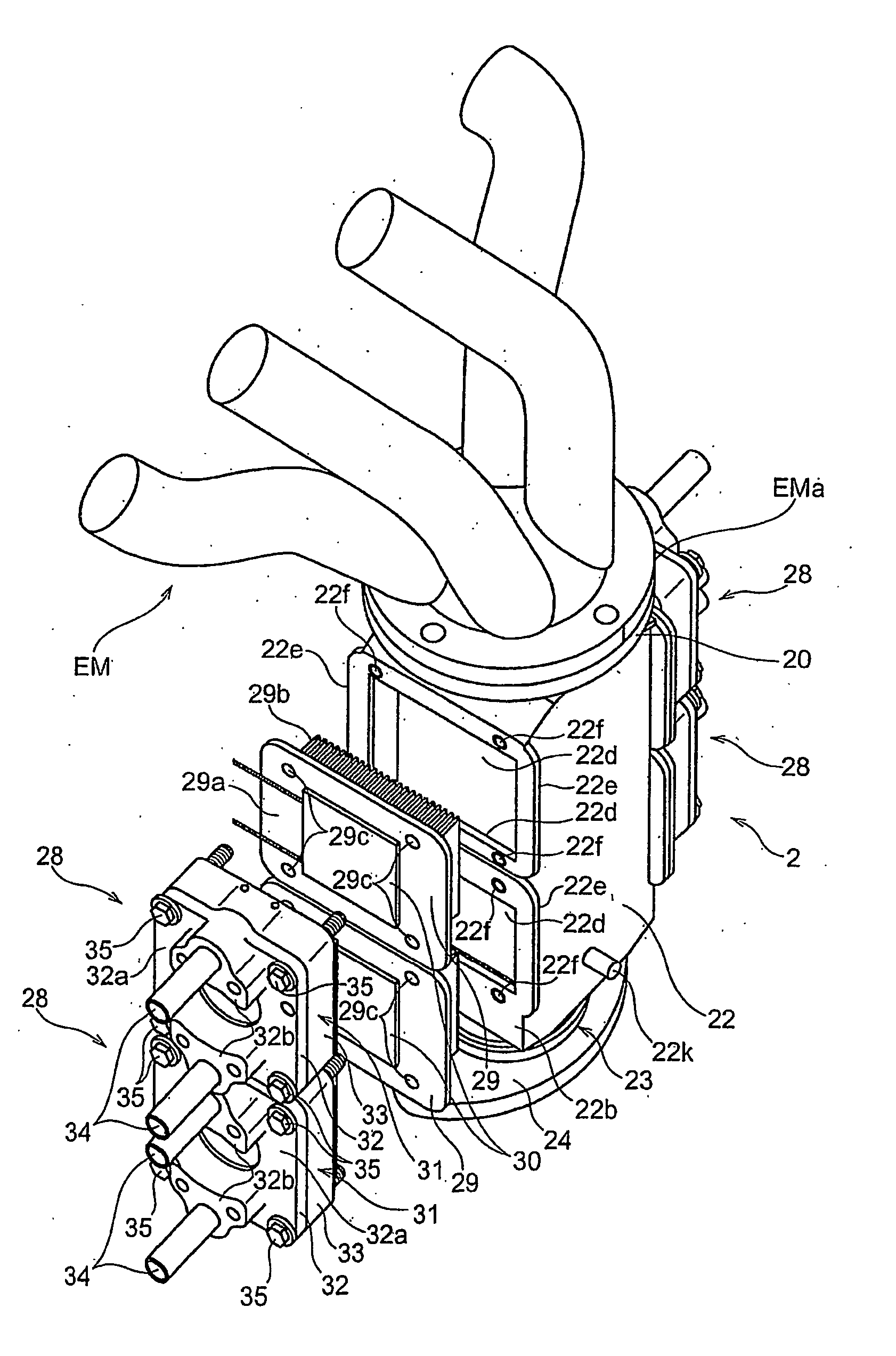
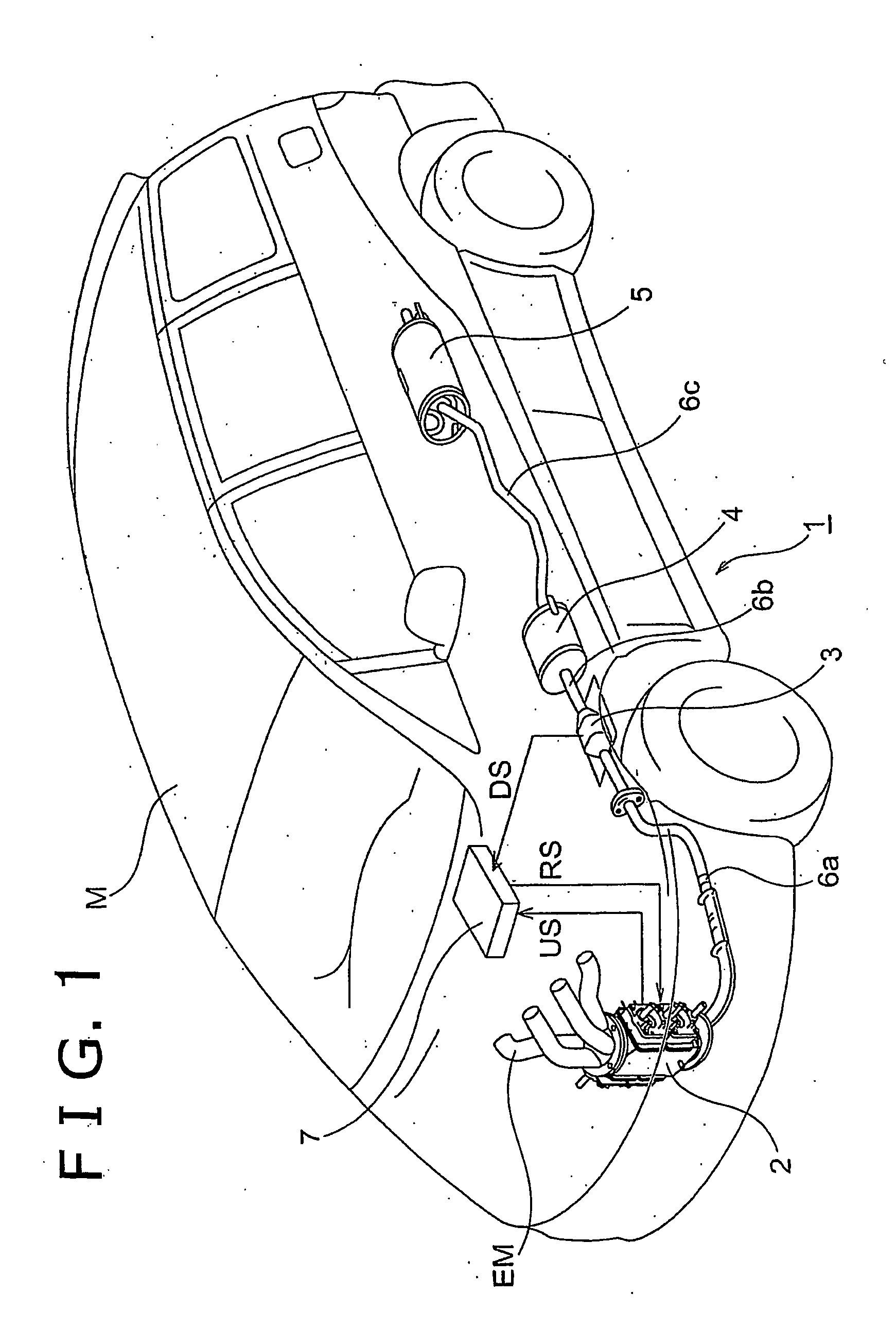
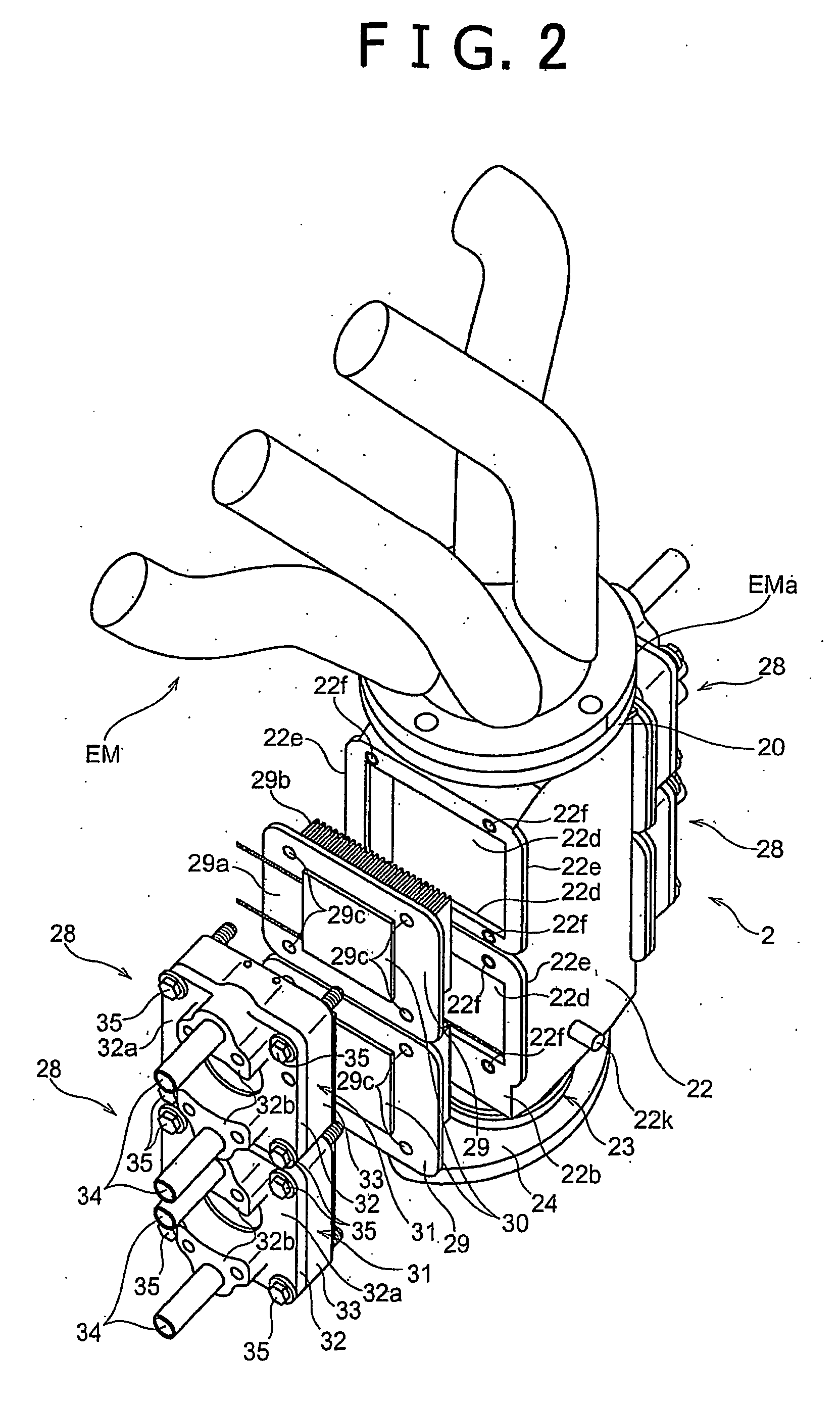
[0039] Embodiments of an exhaust system according to the invention will be described referring to the drawings.

[0040] In this embodiment, an exhaust system is mounted on a vehicle for purifying the exhaust gas from the engine while converting the thermal energy of the exhaust gas into electric energy. The exhaust system according to the embodiment is provided with two exhaust emission catalysts, one is placed in the vicinity of the exhaust manifold (hereinafter referred to as an upstream catalyst), and the other is placed downstream thereof (hereinafter referred to as a downstream catalyst). The upstream catalyst in the vicinity of the exhaust manifold is provided with an exhaust heat power generation unit. In this embodiment, no additional exhaust heat power generation apparatus other than the aforementioned exhaust heat power generation unit is provided. In the other embodiment to be described later, an additional, exhaust heat power generation apparatus is provided.

[0041] A str...


PUM


Abstract

An exhaust system (1) is provided with an exhaust passage that allows exhaust gas discharged from an internal combustion engine to pass therethrough, an exhaust emission control unit including a catalyst (2,3) such as a three-way catalyst (27) to purify the exhaust gas, and an exhaust heat collecting unit that converts thermal energy of the exhaust gas into electric energy. The exhaust passage (25) is formed in the center of the exhaust system provided with the exhaust emission control unit. By-pass passages (26) are formed at both sides of the exhaust passage (25) through which the exhaust gas flows without passing through the exhaust emission control unit. The exhaust heat collecting unit (29) is provided on the outer side of each of the by-pass passages (26).

Description

BACKGROUND OF THE INVENTION [0001] 1. Field of Invention [0002] The invention relates to an exhaust system that purifies exhaust gas using catalyst and converts thermal energy of the exhaust gas into electric energy. [0003] 2. Description of Related Art [0004] Generally, an exhaust system includes an exhaust emission catalyst such as a three-way catalyst to purify exhaust gas discharged from an engine by removing hazardous substance contained in the exhaust gas, for example, carbon monoxide, hydrocarbon, nitrogen oxides and the like. The catalyst becomes effective to purify the exhaust gas when it is activated at its activated temperature in the range between 350° C. and 800° C., for example. [0005] Substantially high thermal energy of the exhaust gas at a high temperature is partially used for increasing the temperature of the exhaust emission catalyst until it reaches the activated temperature. The rest of the thermal energy of the exhaust gas, however, is dispersed without being ...

Claims


Application Information

Patent Timeline
Patent Type & Authority Applications(United States)
IPC IPC(8): F01N3/00F01N3/20F01N3/24F01N5/02F01N3/28F01N13/08F02G5/02F02G5/04H01L35/28H01L35/30H02N11/00
CPCF01N3/2053F01N3/2889F01N5/025F01N2240/02F01N2240/04F01N2410/02F01N13/009F28F3/048H01L35/30Y02T10/16Y02T10/166F01N13/017F02G5/02Y02T10/12H10N10/13F01N5/02F01N3/20
Inventor MURATA, KIYOHITO
Owner TOYOTA JIDOSHA KK
Why Eureka
Try Eureka