
Device for compensating for pressure drop

a technology of pressure drop and compensating device, which is applied in the direction of liquid handling, packaging goods, launching weapons, etc., can solve the problems of less serious disturbance, pressure drop can affect the filling process, and thus constitute an uncertainty in the accuracy with which the container can be filled, so as to achieve the effect of free collapsing of the tube portion

Inactive Publication Date: 2006-03-16
ECOLEAN
View PDF21 Cites 4 Cited by
  • Summary
  • Abstract
  • Description
  • Claims
  • Application Information

AI Technical Summary

Benefits of technology

The present invention provides an improved device and system for compensating for pressure drop in a product pipe. The device is easy to clean, has a satisfactory service life, and is inexpensive to manufacture, install, and maintain. The device includes a collapsible tube portion that can be connected to the product pipe and is adapted to compensate for pressure drop by allowing free collapsing of the tube portion while preventing stretching in the tube portion. The limiting means is integrated into the tube portion or arranged outside the tube portion, allowing for easy installation and maintenance. The device and system can efficiently take care of pressure drop in the product pipe and are hygienic and easy to clean. The technical effects of the invention include improved efficiency in compensating for pressure drop, reduced service life costs, and improved food safety.

Problems solved by technology

This pressure drop may cause more or less serious disturbances.
Furthermore the pressure drop can affect the filling process controlled by the filling valve in question.
If the filling valve is time-controlled, the pressure drop thus constitutes an uncertainty with regard to the accuracy with which the container can be filled.
The container can either be filled with too small or too large an amount of liquid.
This surge can be detrimental to the filling station and also affect the filling processes at other filling stations connected to the product pipe.
The construction, however, suffers from the drawback that it is difficult to clean and sterilise, which are important aspects in systems for filling of containers with liquid food contents.
The construction is also relatively expensive to manufacture and install.
The device according to SE 410,844, however, has a serious drawback since it has a most limited service life.
Up to now, it has proved difficult to find a material which with an acceptable service life can be subjected to such strain.
The device described in U.S. Pat. No. 6,264,069, however, involves problems similar to those of the device of SE 410,844, i.e. the repeated stretching of the inner tube causes it to obtain a short service life.
Also this device has the problem of a short service life since the inner tube is stretched repeatedly.
When a surge arises in a system, the flexible tube expands and, thus, dampens the surge.
The hose of JP 3,175,599 is not intended to affect the pressure of a system, but still obtains a short service life caused by the repeated stretchings.

Method used


Image

  • Device for compensating for pressure drop
  • Device for compensating for pressure drop
  • Device for compensating for pressure drop

Examples


first embodiment

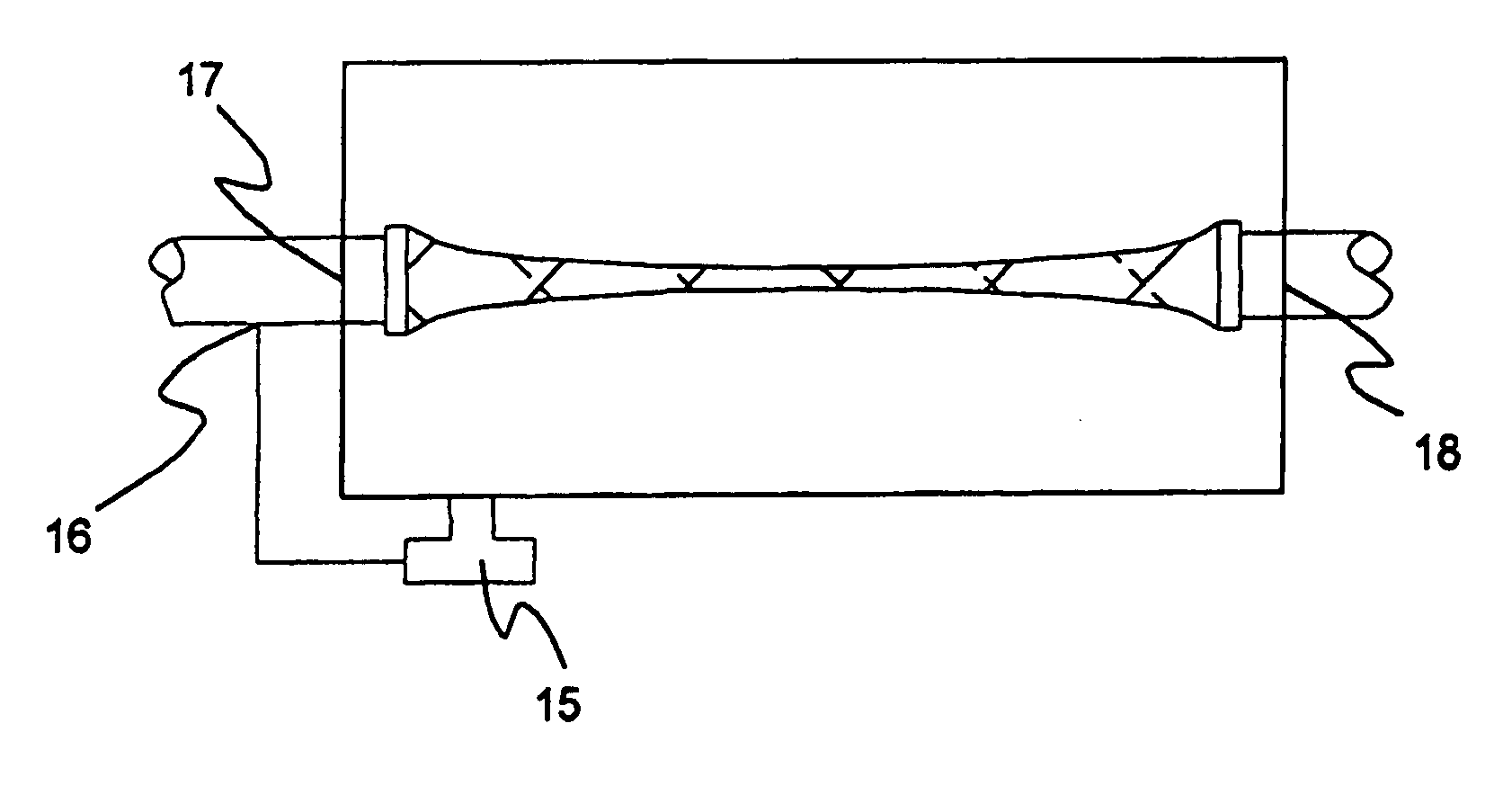
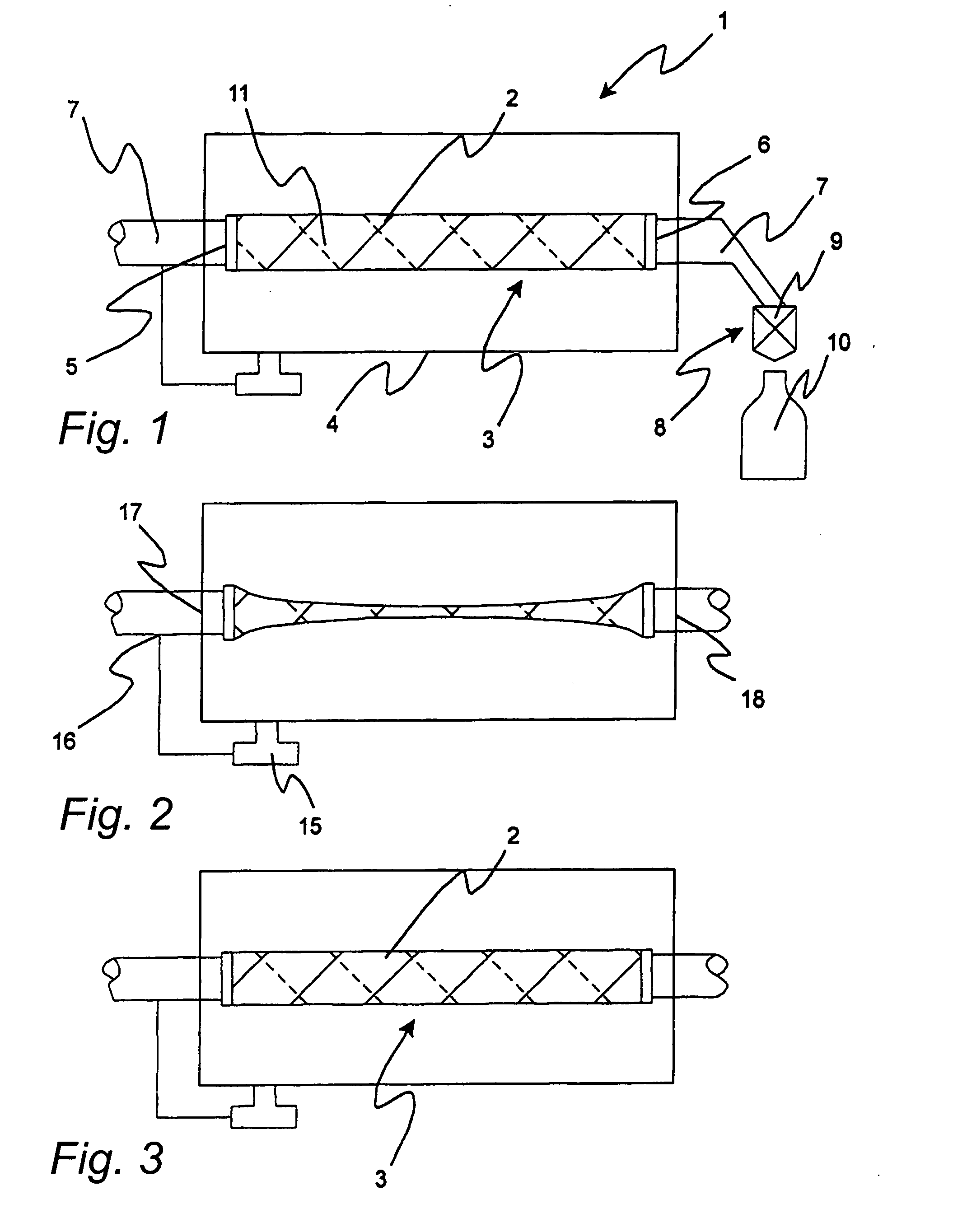
[0053]FIG. 1 to which reference is made, illustrates an inventive device 1.

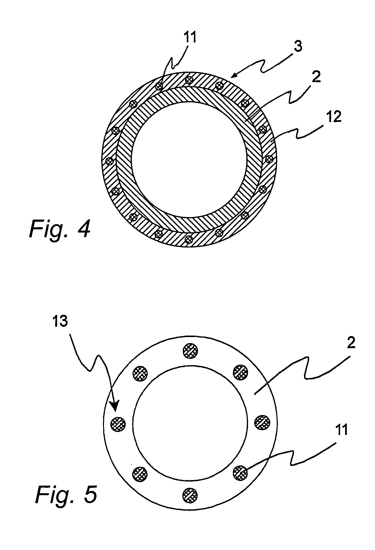
[0054] The device 1 comprises as main components a flexible tube portion 2, a limiting means 3 arranged outside the same and a casing 4 which encloses said tube portion 2 and said limiting means 3.

[0055] The shown embodiment of the inventive device 1 comprises an inlet 5 and an outlet 6 through which the device 1 is connected to a product pipe 7 in such a manner that the tube portion 2 of the device 1 forms part of the flow path of the product pipe 7. The part of the product pipe 7 which extends from the outlet 6 of the device 1 leads to a filling station 8 which is schematically shown in the form of a filling valve 9. The filling valve 9 is openable to allow discharge of a product flowing in the product pipe 7, for instance for filling a container 10.

[0056] The tube portion 2 is made of a flexible material which is stretchable in the circumferential direction and tends to collapse when applying a pressure ...


PUM

PropertyMeasurementUnit
pressureaaaaaaaaaa
angleaaaaaaaaaa
angleaaaaaaaaaa

Abstract

The invention relates to a device for compensating for pressure drop in a product pipe through which a liquid flows, and a system comprising such a device. The device comprises a collapsible tube portion, which is connectible to the product pipe, and is characterised by a limiting means, which is adapted to counteract stretching of the tube portion in the circumferential direction and which is adapted to allow free collapsing of the tube portion.

Description

FIELD OF THE INVENTION [0001] The present invention relates to a device for compensating for pressure drop in a product pipe through which a liquid flows, and a system for filling containers comprising such a device. The invention concerns more specifically such a device comprising a collapsible tube portion which is connectible to a product pipe. BACKGROUND ART [0002] A device for compensating for pressure drop in a product pipe through which a liquid flows is used, for instance, in the food industry for filling containers in a filling machine. [0003] The filling machine is connected to the product pipe and has a filling station, at which liquid contents, such as milk or fruit juice, are introduced into the empty containers. To this end, the filling station usually comprises a filling pipe which via a filling valve is connected to the product pipe. For filling a container the filling pipe is inserted into the container, after which the filling valve is opened. When the filling valv...

Claims


Application Information

Patent Timeline
Patent Type & Authority Applications(United States)
IPC IPC(8): F16L11/00B64D1/08B65B37/00B65B3/06B67C3/12B67C3/28B67D1/10F16L55/04
CPCF16L55/04B67C3/28
Inventor GUSTAFSSON, PER
Owner ECOLEAN
Learn More