Apparatus and method for dissipating a portion of the commutation derived collapsing field energy in a multi-phase unipolar electric motor

Inactive Publication Date: 2006-03-16
PETERSEN TECH
View PDF6 Cites 14 Cited by
  • Summary
  • Abstract
  • Description
  • Claims
  • Application Information

AI Technical Summary

Benefits of technology

[0023] The result is a substantial decrease in both the amplitude and duration of the back EMF spike to an extent diminishing its energy to levels readily managed by the power switching devices. The approach at hand is generally referred to as a “biphase unipolar drive” or “BUD”. Where generally lower voltage motors are configured with the BUD technology typically, field effect transistors (FET) are employed as the switching devices. It has been found to be beneficial in certain applications to locate a small capacitor across the switch terminals for these lower voltage motors. A capacitance value of about 0.1 uf is contempl

Problems solved by technology

The result is a substantial decrease in both the amplitude and duration of the back EMF spike to an extent diminishing its energy to levels readily man

Method used


Image

  • Apparatus and method for dissipating a portion of the commutation derived collapsing field energy in a multi-phase unipolar electric motor
  • Apparatus and method for dissipating a portion of the commutation derived collapsing field energy in a multi-phase unipolar electric motor
  • Apparatus and method for dissipating a portion of the commutation derived collapsing field energy in a multi-phase unipolar electric motor

Examples


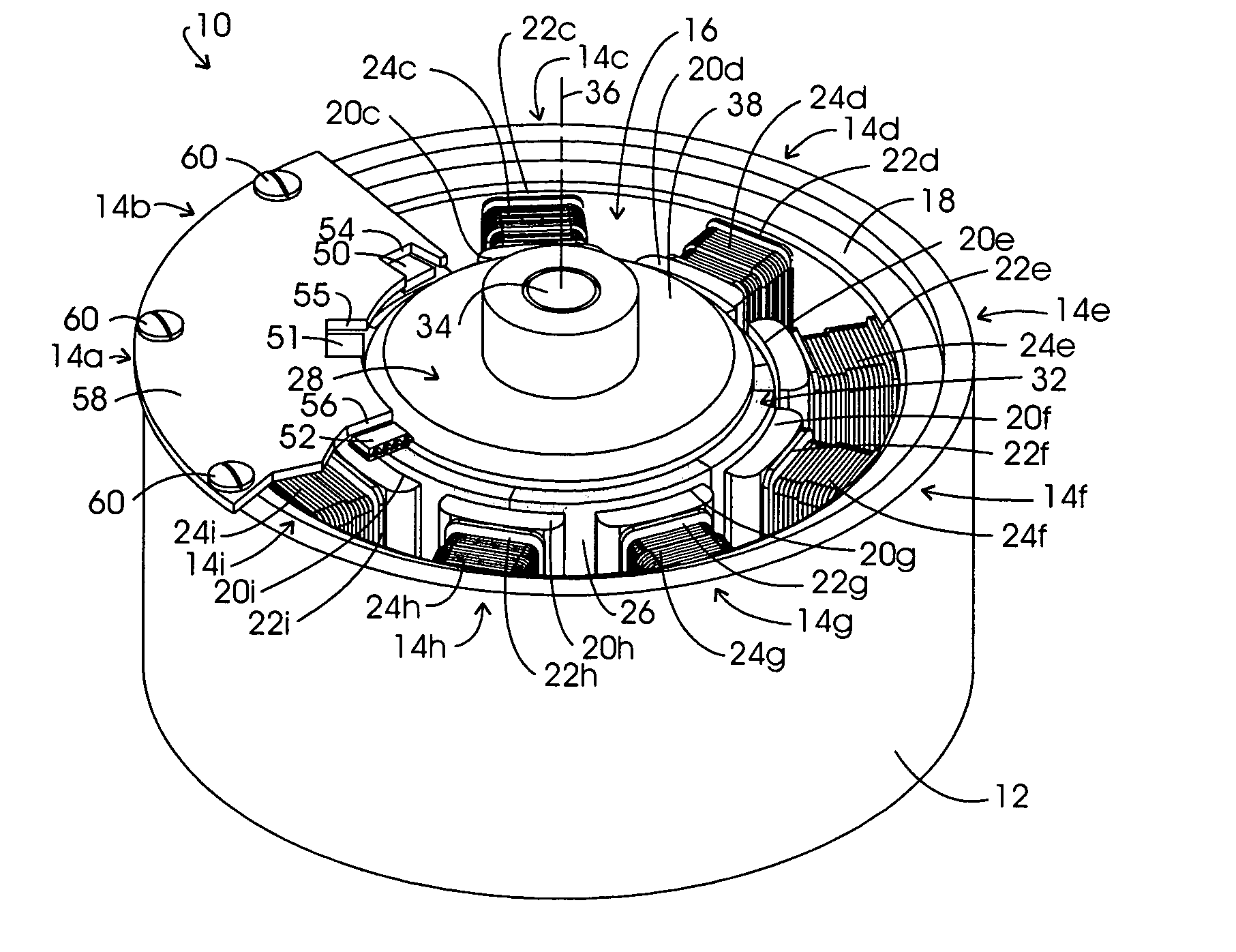
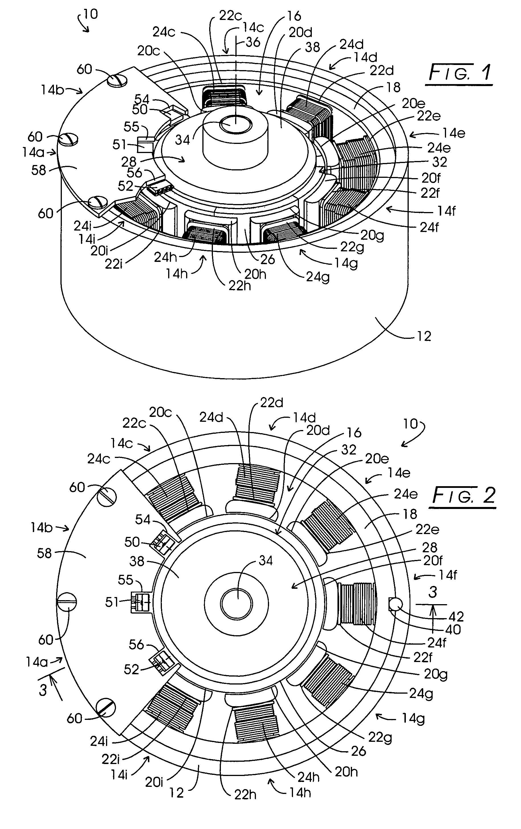
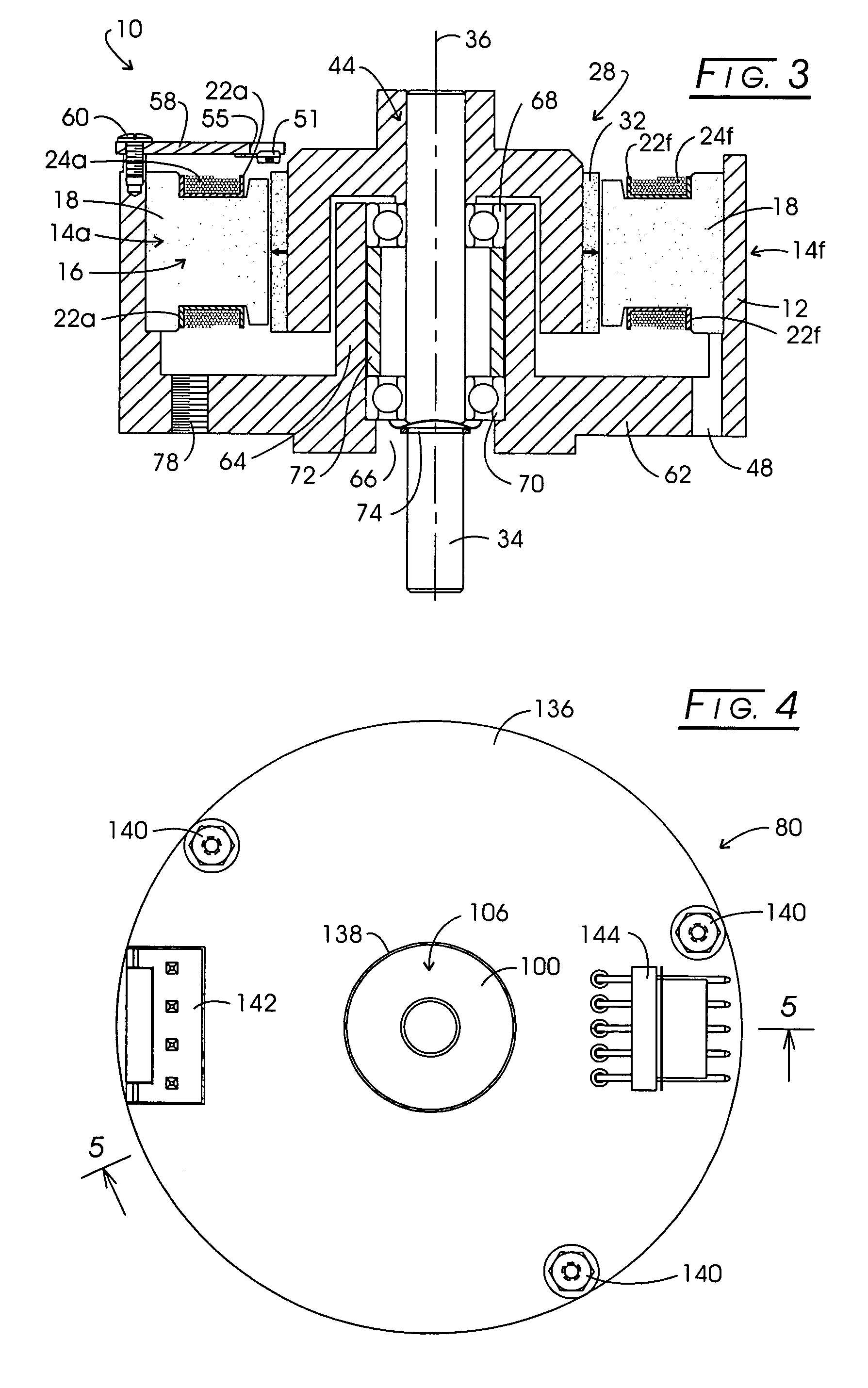
Embodiment Construction

[0060] In the discourse to follow, the architecture of two electronically commutated d.c. PM motors employed in testing in effect three motors, one with the 3-phase unipolar configuration and methodology of the invention, the same motor with a conventional 3-phase unipolar structuring, and a larger 3-phase unipolar motor configured according to the invention are described. Next, the discussion turns to the circuitry and winding topology of motors configured in accordance with the invention, whereupon a representative motor schematic layout and torque curve diagram is discussed with respect to a 3-phase unipolar or single sided drive motor employing the features of the invention. A more detailed electrical schematic of such a motor then is illustrated whereupon an electrical schematic diagram is provided showing a test setup with respect to either of the earlier-described motors employing the methodology of the invention. The discourse ends with an oscilloscope trace-based comparativ...


PUM


Abstract

A multi-phase unipolar motor is configured such that each stator pole is formed with bifilar wound primary and inductively associated secondary windings corresponding with one phase. The primary winding at one stator pole corresponding with one phase is coupled with a secondary winding at another stator pole corresponding with another phase to provide a commutational-step defined winding pair. The resultant winding pair assemblage is energized in correspondence with a commutational sequence such that collapsing field energy may be transferred from a primary winding at the termination of one step in the commutational sequence to the secondary winding associated with it in a next succeeding commutational step.

Description

CROSS-REFERENCE TO RELATED APPLICATIONS [0001] This application claims the benefit of provisional Application No. 60 / 610,155, filed Sep. 15, 2004, the disclosure of which is hereby incorporated by reference.STATEMENT REGARDING FEDERALLY SPONSORED RESEARCH [0002] Not applicable. BACKGROUND OF THE INVENTION [0003] Investigators in the electric motor arts have been called upon to significantly expand motor technology from its somewhat static status of many decades. Improved motor performance particularly has been called for in such technical venues as computer design and secondary motorized systems carried by vehicles, for example, in the automotive and aircraft fields. With progress in these fields, classically designed electric motors, for example, utilizing brush-based commutation, while relatively inexpensive, have been found to be unacceptable or, at best, marginal performers. [0004] From the time of its early formation, the computer industry has employed brushless d.c. motors for...

Claims


Application Information

Patent Timeline
IPC IPC(8): H02K21/12H02K3/00H02P7/06
CPCH02K3/28H02K5/225H02P8/12H02K29/08H02K21/16
Inventor PETERSEN, CHRISTIAN C.
Owner PETERSEN TECH
Why Eureka
Try Eureka