Battery charged condition computing device and battery charged condition computing method

a technology of condition computing and battery, which is applied in the direction of testing electric installations on transportation, transportation and packaging, instruments, etc., can solve the problems of large judgment error of charging state and difficulty in accurately estimating battery remaining capacity, and achieve the effect of short time and easy judgmen

Inactive Publication Date: 2006-03-16
MITSUBISHI ELECTRIC CORP +1
View PDF2 Cites 31 Cited by
  • Summary
  • Abstract
  • Description
  • Claims
  • Application Information

AI Technical Summary

Benefits of technology

[0024] The battery charging state arithmetic operation device of the invention includes the battery voltage detection means for detecting the voltage of the battery, the battery current detection means for detecting the current of the battery, the first current-voltage characteristic storage means for approximately obtaining the current-voltage characteristic of the battery in the first state as the currently used state by using the voltage values and the current values detected by the battery voltage detection means and the battery current detection means at the plural sampling points and for storing it as the first current-voltage characteristic, the second current-voltage characteristic storage means for previously storing the second current-voltage characteristic in the second state where the amount of extractive energy is smaller than that in the first state, the specified current value storage means for storing the specified load current value of the battery, the battery voltage calculation means with specified load for calculating the first battery voltage when the battery current is at the

Problems solved by technology

However, since the open-circuit voltage of the battery is greatly influenced by the charging, and discharging history up to that time, about one day is required before it becomes stable, and when the charging state during driving is corrected on the basis of the open-circuit voltage immediately before the driving, a judgment error of the charging

Method used


Image

  • Battery charged condition computing device and battery charged condition computing method
  • Battery charged condition computing device and battery charged condition computing method
  • Battery charged condition computing device and battery charged condition computing method

Examples


embodiment 1

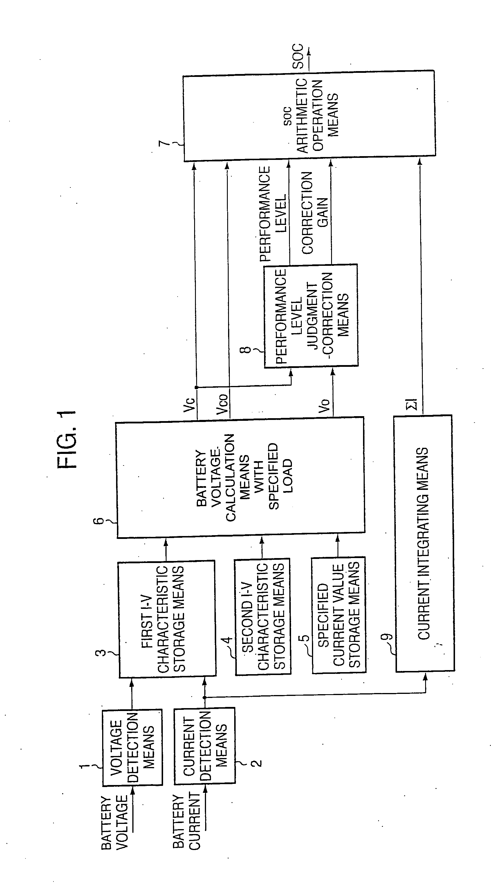
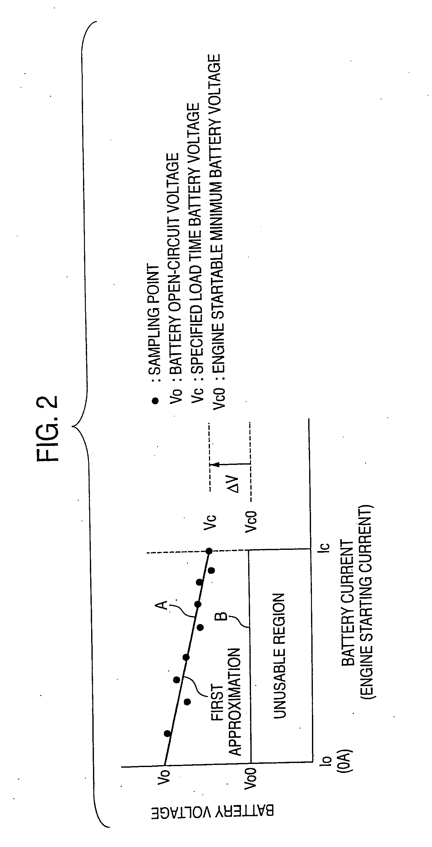
[0037]FIG. 1 is a block diagram showing a structure of a battery charging state arithmetic operation device according to embodiment 1. FIG. 2 is a diagram for explaining an operation of the battery charging state arithmetic operation device according to this embodiment.

[0038] The structure and the operation of the battery charging state arithmetic operation device according to this embodiment will be described with reference to FIGS. 1 and 2.

[0039] In FIG. 1, reference numeral 1 denotes voltage detection means for detecting a battery voltage of a battery (not shown) mounted in a hybrid car, an electric vehicle, an idle stop vehicle or the like; 2, current detection means for detecting a charging and discharging current of the battery; and 3, first current (I)-voltage (V) characteristic storage means of the battery. Hereinafter, the “current-voltage characteristic” will be referred to as the “I-V characteristic”.

[0040] The first I-V characteristic storage means 3 stores battery vo...

embodiment 2

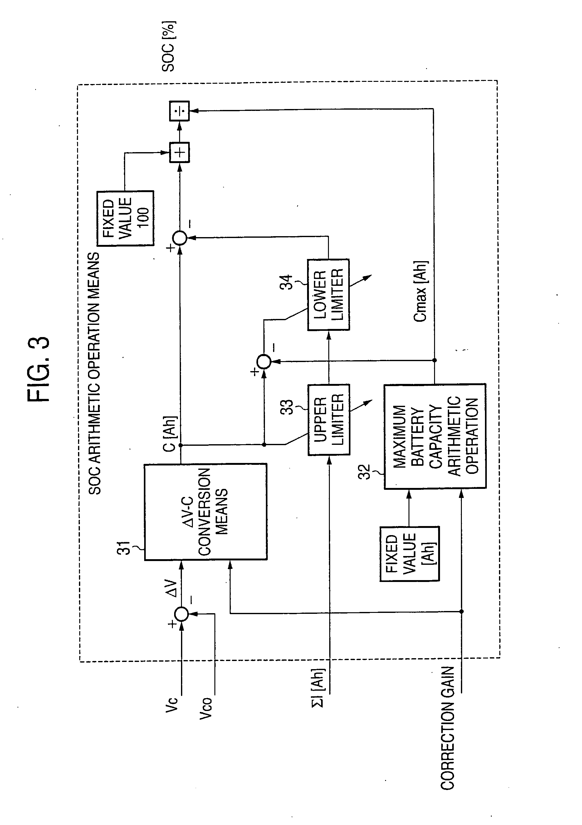
[0055]FIG. 3 is a block diagram showing a structure of the SOC arithmetic operation means 7 shown in FIG. 1 and according to embodiment 2.

[0056] In FIG. 3, reference numeral 31 denotes ΔV-C conversion means for obtaining a battery charging state C from a voltage difference (Vc−Vc0) ΔV between the first battery voltage Vc already explained in FIG. 1 and the second battery voltage Vc0 similarly already explained in FIG. 1; 32, maximum battery capacity arithmetic operation means for obtaining a maximum battery capacity Cmax which is obtained by multiplying a nominal battery capacity of the battery by a correction gain explained in FIG. 4; 33, an upper limiter for limiting a current integration value ΣI by the previously obtained battery charging state C; and 34, a lower limiter for limiting the previously limited ΣI by what is obtained by subtracting the previously obtained maximum battery capacity Cmax from the previously obtained battery charging state C.

[0057] Next, this embodimen...

embodiment 3

[0060]FIG. 4 is a block diagram showing a structure of the performance level judgment-correction means 8 shown in FIG. 1 and according to embodiment 3.

[0061] Reference numeral 41 denotes performance level judgment means for obtaining a performance level from the first battery voltage Vc and the battery voltage Vo when the battery current is zero (load opening time) in the first I-V characteristic; and 42, performance level correction gain calculation means for obtaining a correction gain from the performance level obtained by the performance level judgment means 41.

[0062] Next, this embodiment will be described. The performance level of the battery currently being used is detected from the first battery voltage Vc and the battery voltage Vo when the battery current is zero (load opening time) in the first I-V characteristic and by using the performance level detection means 8. In the case where the open circuit voltage is plotted on the horizontal axis while the first battery volt...


PUM


Abstract

In order to provide a battery charging state arithmetic operation device which can judge a charging state of a battery currently being used easily and in a short time, there are provided battery voltage calculation means 6 with specified load for calculating a first and a second battery voltages when a battery current is at a specified load current value from a first I-V characteristic of the battery which is in a first state as a currently used state and is stored in first I-V characteristic storage means 3 and a second I-V characteristic which is in a second state where the amount of remaining energy is small and is stored in second I-V characteristic storage means 4, and SOC arithmetic operation means 7 for calculating an SOC (charging state) of the battery in the first state by using the first and the second battery voltages calculated.

Description

TECHNICAL FIELD [0001] The present invention relates to a battery charging state arithmetic operation device to detect the state of a remaining capacity (that is, charging state) in a state where a battery used for a vehicle or the like is being used, and a battery charging state arithmetic operation method. BACKGROUND ART [0002] As a conventional estimating method of the remaining capacity of a battery (that is, an estimating method of the charging state of a battery), there is generally known a method in which a battery terminal open-circuit voltage is made as an initial value of the charging state (SOC: State of Charge) of the battery, and a correction is made using an integration value of battery charging / discharging current. [0003] Besides, JP-A-2001-174535 (FIG. 1 and paragraph 0039) discloses “a battery capacity arithmetic operation device in consideration of polarization” in which an accurate I-V (current-voltage) approximate straight line in consideration of polarization of...

Claims


Application Information

Patent Timeline
IPC IPC(8): H02J7/00G01R31/00G01R31/36
CPCG01R31/006G01R31/3651G01R31/3624G01R31/3842G01R31/367
Inventor FUJIHARA, SHINJIANZAI, KIYOHARUKIRIBAYASHI, MOTOSHIWANEZAKI, MAKOTONAKAMURA, HIDEJIHAYASHI, TOSHIAKI
Owner MITSUBISHI ELECTRIC CORP
Why Eureka
Try Eureka