Eureka AIR delivers breakthrough ideas for toughest innovation challenges, trusted by R&D personnel around the world.

Recording liquid, liquid cartridge, liquid discharge apparatus and method of liquid discharge

a liquid discharge apparatus and liquid discharge technology, applied in the direction of instruments, inks, measurement apparatus components, etc., can solve the problems of ink in the ink duct being extremely prone to temperature rise, degrading printing quality, and printing image suffering from white spots, so as to prevent fine bubbles, eliminate blurring or generation of white spots, and prevent emission defects

Inactive Publication Date: 2006-03-16
SONY CORP
View PDF1 Cites 6 Cited by
  • Summary
  • Abstract
  • Description
  • Claims
  • Application Information

AI Technical Summary

Benefits of technology

The present invention provides a recording liquid that overcomes problems of the related art, such as foaming, stability, and color mixing. The recording liquid contains an ethylene oxide adduct of a dihydric alcohol with a hydrocarbon group of 9 or less carbon atoms and a ratio of inorganic value to organic value not less than 1 and not larger than 1.37. The recording liquid also exhibits high optical density and is free of boundary bleeding and speckled color mixing in all-over printing. The invention also includes a liquid cartridge and a liquid emitting device for high-quality printing.

Problems solved by technology

When these fine bubbles are present in the ink emitting head, emission troubles, such as non-emission of the ink from the nozzle or warped emission of the ink, that is, the ink being emitted from the nozzle along a path offset from the intended path, are produced, with the result that printed image suffers from white spots or becomes blurred to degrade the printing quality.
Thus, heat is accumulated in the vicinity of the heater, and hence the ink in the ink duct is extremely liable to be raised in temperature, with the result that emission troubles, such as the aforementioned non-emission or warped emission, tend to be produced to a pronounced extent.
However, these proposals are not up to sufficient suppression of fine bubbles and further improvement has been desired.
However, if a compound obtained on adding only ethylene oxide to the higher alcohol a dihydric alcohol alkoxylate is contained in the ink, in association with the teaching by Patent Publication 1, it has not been possible to cope successfully with the problem of the nozzles being stopped with fine bubbles.
Specifically, the ink obtained on adding 7 mol or more only of ethylene oxide undergoes vigorous foaming to cause severe nozzle clogging.
However, neither of these Publications is sufficient to meet the aforementioned demand and further improvement has been desired.
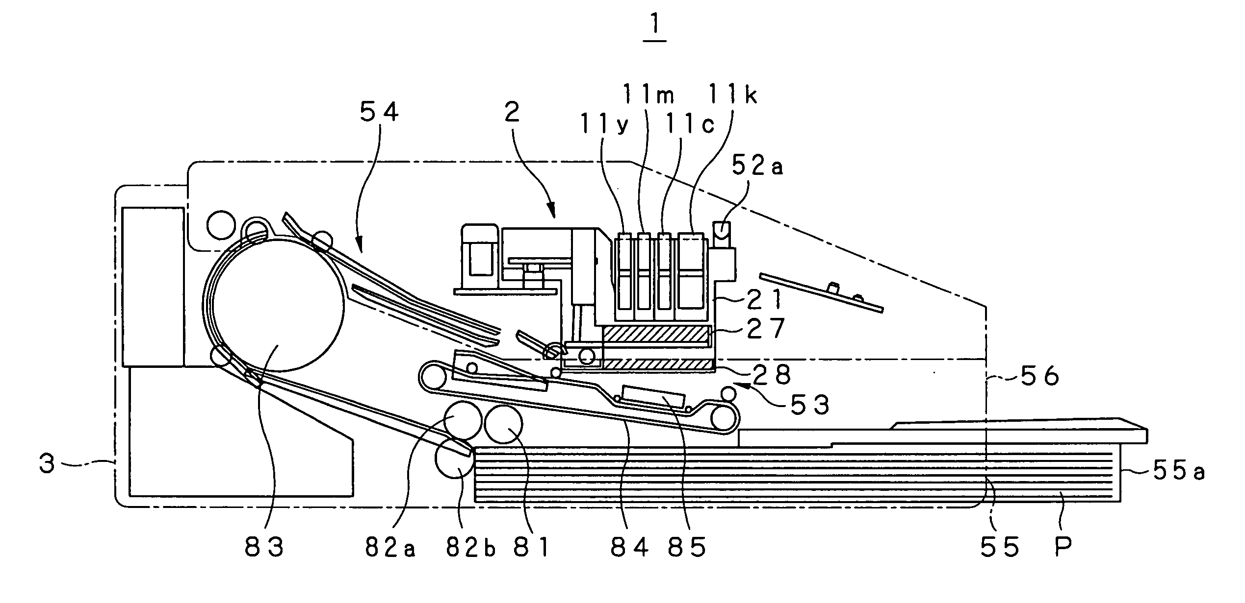
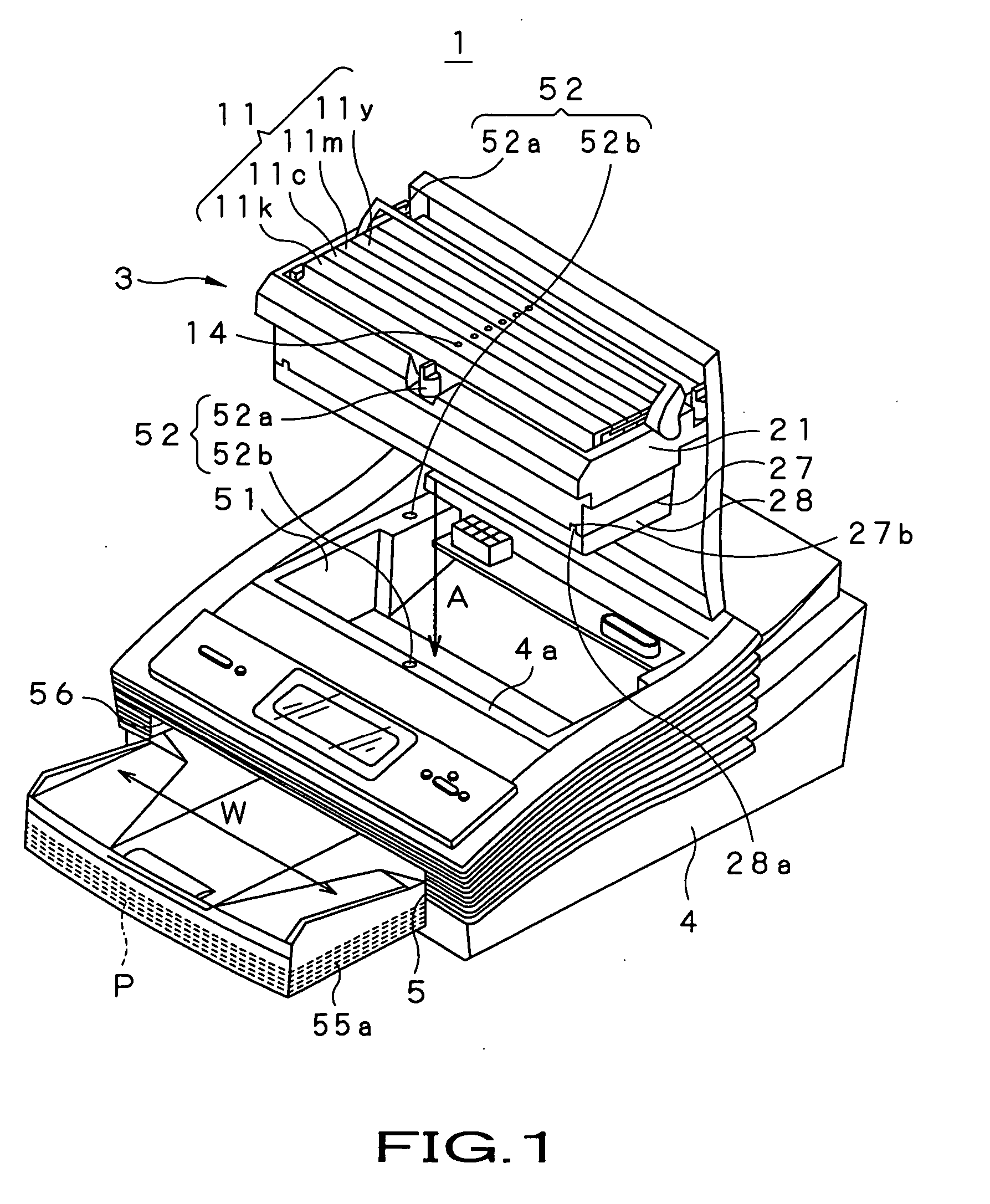
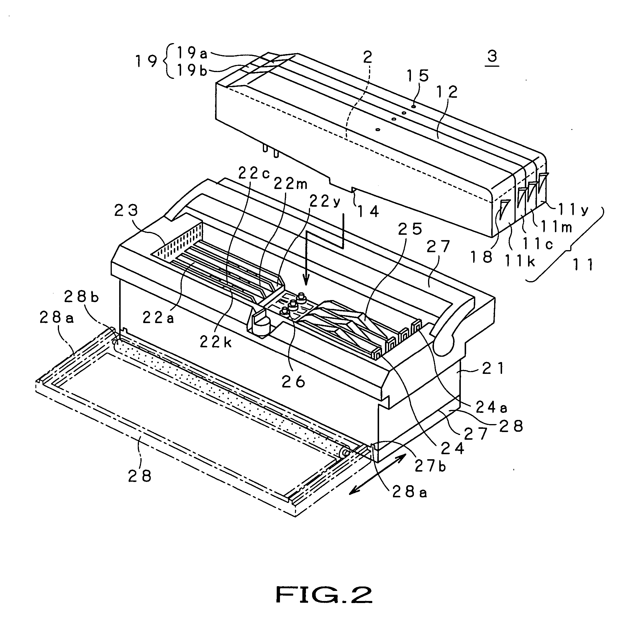
On the other hand, the aforementioned problem, related with the bubbles, occurs more pronouncedly with a printer apparatus capable of performing high-speed printing on a recording paper sheet, that is, a line-based printer apparatus having an ink emitting range substantially equal to the width of the recording paper sheet (for example, see Patent Publications 7 to 9).
Moreover, the ink tank is separated from the ink emitting head a long distance, whilst the structure from the ink tank to the ink emitting head is complicated to render it difficult to remove the fine bubbles generated, with the result that inconveniences ascribable to the fine bubbles occur most pronouncedly.
In addition, if so-called color printing of emitting inks of different colors on a recording paper sheet, is to be carried out with the line-based printer apparatus, where the period of emission of liquid droplets from one nozzle line to the next is short, a color liquid droplet is deposited before the previously deposited color liquid droplet sufficiently seeps into the bulk part of the paper sheet, with the consequence that boundary bleeding or speckled color mixing in all-over printing tends to be produced between different colors.

Method used


Image

  • Recording liquid, liquid cartridge, liquid discharge apparatus and method of liquid discharge
  • Recording liquid, liquid cartridge, liquid discharge apparatus and method of liquid discharge
  • Recording liquid, liquid cartridge, liquid discharge apparatus and method of liquid discharge

Examples


example

[0158] The present invention will now be explained with reference to samples of an ink actually prepared as a recording liquid embodying the present invention.

[Sample 1]

[0159] In the sample 1, a magenta-based ink was first prepared. For preparing the magenta-based ink, 3 mass wt % of C.I. Acid red, as a colorant, 75 mass wt % of water, as a solvent, 10 mass wt % of glycerin, as another solvent, 5 mass wt % of 1,3-butanediol, as another solvent, 5 mass wt % of neopentyl glycol, as yet another solvent, and 1.5 mass wt % of the compound shown by the above chemical formula 4, were mixed together and filtered by a membrane filter, with a pore size of 0.22 μm (trade name: Millex-0.22), to prepare a magenta-based ink.

[0160] Then, a cyan-based ink was prepared. For preparing the cyan-based ink, 2.5 mass wt % of C.I. Direct Blue, as a colorant, 76 mass wt % of water, as a solvent, 10 mass wt % of glycerin, as another solvent, 5 mass wt % of 1,3-butanediol, as another solvent, 5 mass wt % ...


PUM

PropertyMeasurementUnit
dynamic surface tensionaaaaaaaaaa
optical densityaaaaaaaaaa

Abstract

According to the present invention, an ink (2) containing an EO adduct of a dihydric alcohol, having a hydrocarbon group with 9 or less carbon atoms and having an I / O ratio ranging between 1 and 1.37, is supplied via nozzles (42a) in the form of liquid droplets i onto a recording paper sheet P, so that fine bubbles may be suppressed from being generated in the ink (2) to prevent emission defects such as non-emission or warped emission, and hence a high quality image free of blurring or white spots may be produced.

Description

TECHNICAL FIELD [0001] This invention relates to a recording liquid deposited on a support in the state of droplets for recording thereon, a liquid cartridge for holding the recording liquid, and to a liquid emitting device and a liquid emitting method for emitting the recording liquid, contained in the liquid cartridge, as droplets through an emitting opening onto the support. [0002] This application claims priority of Japanese Patent Application No. 2003-360027, filed in Japan on Oct. 20, 2003, the entirety of which is incorporated by reference herein. BACKGROUND ART [0003] As a liquid emitting device, there is an ink jet printer apparatus in which a recording liquid, or a so-called ink, is emitted via an ink emitting head to a recording paper sheet, as a support, to record an image or a letter / character thereon. The printer apparatus of the ink jet system has advantages such as low running costs, small size, and ease in printing a colored image. [0004] The ink jet system, emittin...

Claims


Application Information

Patent Timeline
Patent Type & Authority Applications(United States)
IPC IPC(8): G01D11/00B41J2/175B41J2/19C09D11/00
CPCB41J2/1752C09D11/30B41J2/19B41J2/17553
Inventor SEKIGUCHI, HIDEKITANAKA, YASUHIROFURUKAWA, NORIAKI
Owner SONY CORP
Why Eureka
Eureka Blog
Learn More