Methods for earth modeling and seismic imaging using interactive and selective updating

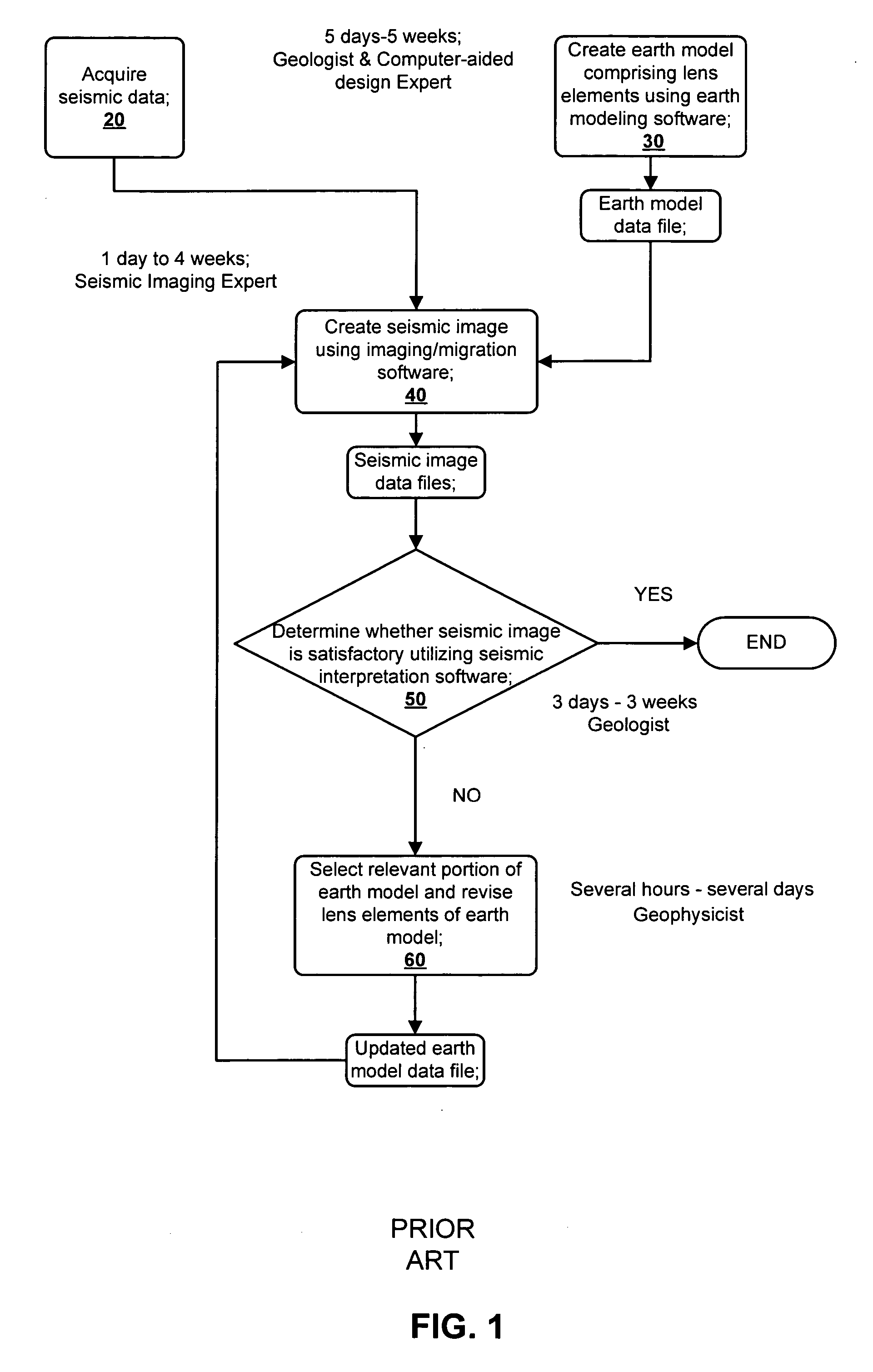
a technology of seismic imaging and earth modeling, applied in the field of earth modeling and seismic imaging, can solve the problems of affecting the propagation direction of seismic energy, image will not usually be well focused everywhere, and tomography is only appropriate,

Active Publication Date: 2006-03-16
CHEVROU USA INC
View PDF21 Cites 70 Cited by
  • Summary
  • Abstract
  • Description
  • Claims
  • Application Information

AI Technical Summary

Benefits of technology

[0030] A method for creating an enhanced seismic image is described. Ideally, an earth model will concurrently be enhanced in quality. Seismic data are acquired from a seismic survey conducted over a subterranean region. The seismic data are transformed into energy components, preferably Gaussian beam components. An earth model is created which is comprised of lens elements having propagation properties, such as velocity and shape, which affect energy propagation through the lens elements. The energy components are propagated or migrated through the lens elements to form image components which are combined into a seismic image.
[0034] Ray tracing may be used to select the trial set of lens elements to be updated and also to select the trial set of energy components. The preferred energy components are Gaussian beam components and the preferred propagation or migration technique used is Gaussian beam migration. The iterative updating of the seismic image is performed within a single application so that data files do not have to be passed between separate software packages.
[0035] It is an object of the present invention to provide an integrated workflow in earth modeling and seismic imaging program wherein the computational time required to update earth models and seismic images is sufficiently short that this workflow can be accomplished interactively in minutes or hours rather than using discretized programs and analyses which require weeks or months to complete.
[0038] Still a further object is to update an earth model using not only information from structural patterns emerging in the image but also by a quick ray-trace analysis of imaging focusing.

Problems solved by technology

Moreover, the shapes of the boundaries between various geologic layers can greatly affect the propagation direction of seismic energy as well.
The imaging program will produce an image of the sedimentary layers, but the image will not usually be well focused everywhere because the sedimentary velocities are not accurate and especially do not accurately represent lateral spatial velocity variations, such as might be caused by the presence of gas.
At this point, however, tomography is only appropriate for finding velocity corrections for regions above massive salt layers; the salt itself and regions below salt are generally too badly imaged to allow the use of tomographic velocity calculations.
This round of mapping is not as easy as mapping the water bottom because the top of salt is often rugose.
The actual bottom of salt is not yet specified because it is generally not yet well imaged.
Often, however, mapping the salt bottom is very difficult and ambiguous.
The salt bottom is not well illuminated everywhere because the salt top refracts energy in other directions.
Usually, the signal is weak because the salt top interface significantly reduces the energy transmitted to illuminate deeper horizons.
There can also be large coherent noise caused by multiple reflections above the salt and by conversion of the pressure-wave seismic energy to shear-wave seismic energy.
Although these factors make the identification of the salt bottom difficult, the interpreter must nevertheless map the salt bottom and save this map as a computer file.
It is difficult to measure sedimentary velocities beneath salt.
In many other cases, the construction of the velocity model is much more complicated and cannot be described beforehand in a step-by-step recipe.
For example, in thrustbelt geology, there can be overturned layers for which it is difficult to determine both the layer shapes and the velocities within the layers.
In other examples, anhydrates entrained in salt masses have a large effect on the propagation of the seismic energy but are difficult to map from the seismic image.
There are many barriers to improving upon a suboptimal seismic image.
First, it is often not clear what changes should be made to the model to improve the focusing of the image.
Nevertheless, the resolution of these inversion programs is limited.
Furthermore, in many seismic imaging problems, the seismic signal is weak and noise is strong, making it difficult to discern whether the image is focused or not.
Geophysical measurements are usually not sufficient for obtaining an accurate image of complex geology.
Moreover, an image that exhibits superimposed crossing geologic bedding cannot be correct.
Combining geophysical inversion of the seismic data with geologic constraints on the earth model is difficult to derive mathematically and to implement in computer code.
Revising a seismic image with geologic insight is difficult.
This is largely due to the length of time it takes to recompute updated data files, i.e., earth model data files, seismic image data files, and topological subsurface bedding maps.
Commonly, it takes many hours or days for computers to compute these large updated files for each of the earth modeling, seismic imaging, and seismic interpretation steps.
First, the computational efforts to update earth models, seismic images, and maps are great due to the recomputing of the entire data files during iterations.
Second, because each of the updating steps in earth modeling, seismic imaging and seismic interpretation is so time consuming, it is difficult for and unlikely that the various experts will fully collaborate when decisions are made as how to update the earth model and seismic images.

Method used


Image

  • Methods for earth modeling and seismic imaging using interactive and selective updating
  • Methods for earth modeling and seismic imaging using interactive and selective updating
  • Methods for earth modeling and seismic imaging using interactive and selective updating

Examples


Embodiment Construction

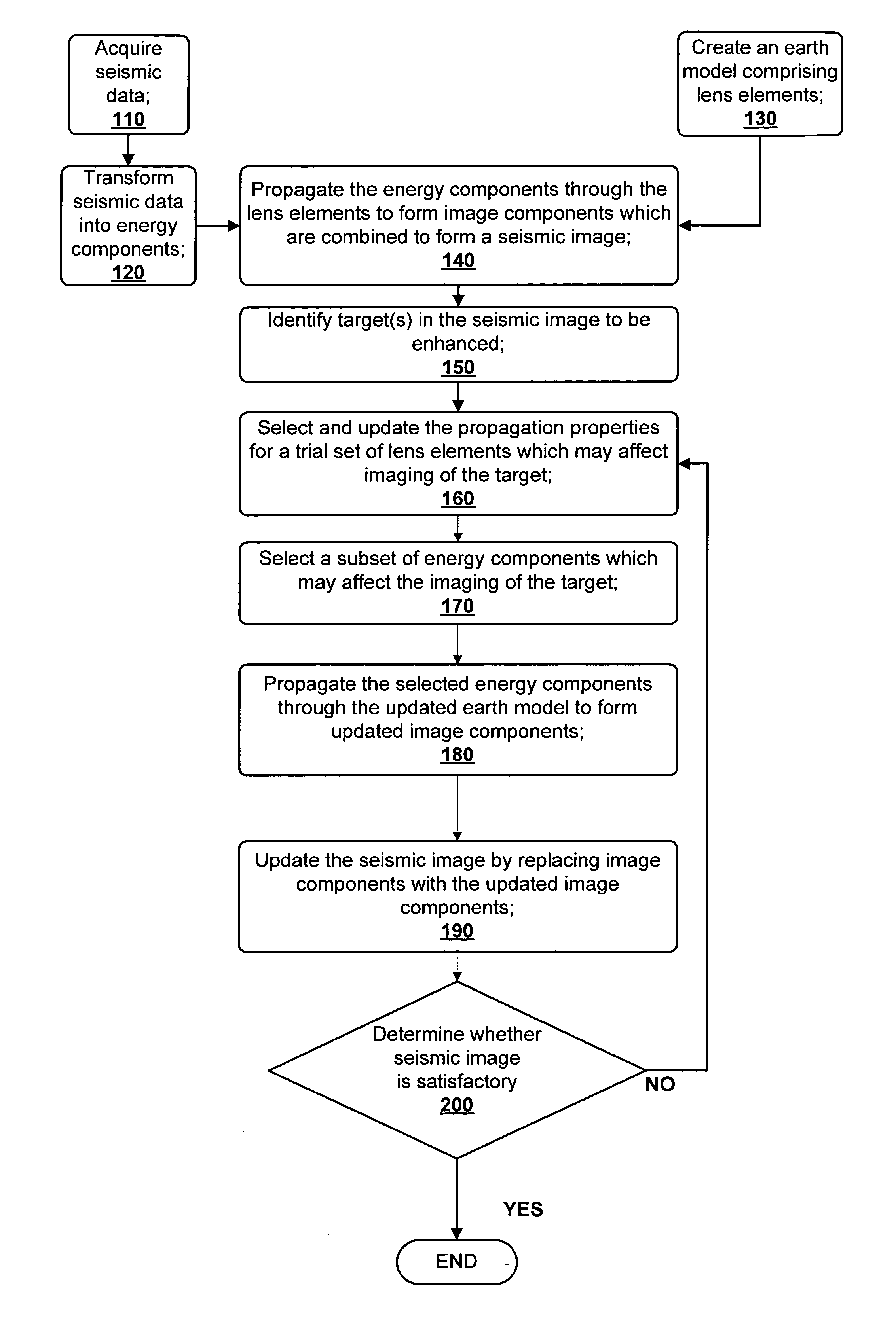
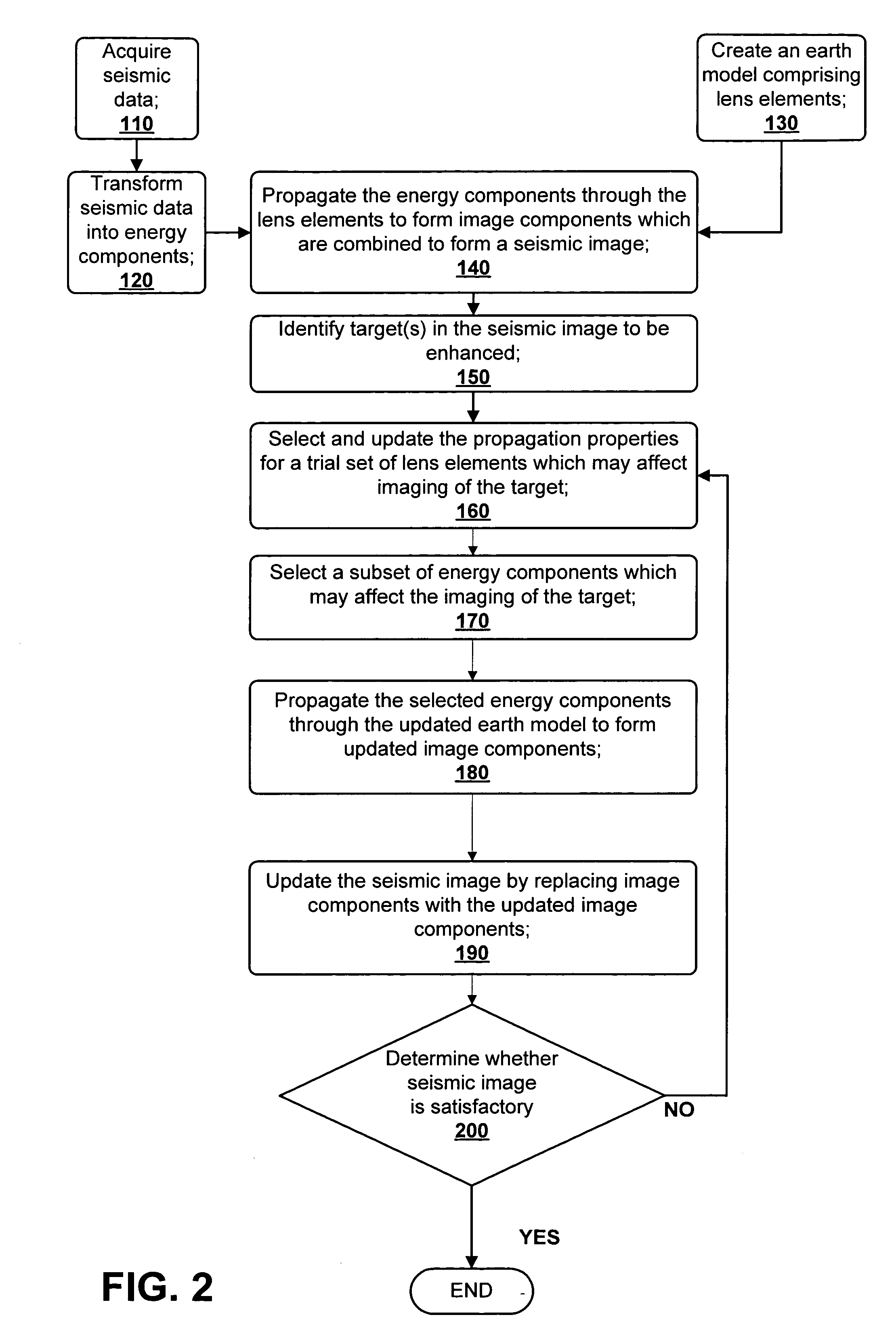
[0051] An exemplary and preferred embodiment of a method for creating an enhanced seismic image, made in accordance with the present invention, is shown in FIG. 2. FIGS. 3 and 4 show sub-steps of steps 160 and 170 of FIG. 2. The method concurrently optimizes an earth model along with the seismic image.

[0052] In step 110, seismic data are obtained from a seismic survey of a subterranean region of interest. The seismic data, if so desired, can be organized into data sets which facilitate further analysis. In this exemplary embodiment, the seismic data is organized into common-offset sections (COS). Alternatively, these seismic data may be used in a raw form by using the recorded organization of the seismic data, i.e., common shot gathers. Or else, the seismic data may be organized into other data sets such as common-midpoint gathers or common-receiver data.

[0053]FIG. 5 shows a two-dimensional example of a COS data set, which, for this particular example, happens to be for zero offse...


PUM


Abstract

A method for creating an enhanced seismic image is described. Seismic data is acquired from a seismic survey conducted over a subterranean region. The seismic data is transformed into energy components, preferably Gaussian beam components. An earth model is created which is comprised of lens elements. The set of energy components is propagated or migrated through the lens elements to form image components which are combined into a seismic image. A target is identified in the seismic image for image enhancement. Ray tracing may be used to select the trial set of lens elements to be updated and to select a subset of energy components. The subset of energy components is propagated through updated earth model to form updated image components. The seismic image is updated by replacing image components with updated image components which are formed from the subset of selected energy components. This subset is ideally greatly reduced in size relative to the overall number of energy components, i.e., beam components.

Description

FIELD OF THE INVENTION [0001] The present invention relates generally to methods for earth modeling and seismic imaging, and more particularly, to methods which use beam migration to create seismic images. BACKGROUND OF THE INVENTION [0002] Constructing accurate seismic images and corresponding earth models is important in making decisions relating to exploration and reservoir management. For example, earth scientists use seismic images to determine where to place wells in subterranean regions containing hydrocarbon reservoirs. They also use velocity or earth models to create reservoir models suitable for reservoir fluid flow modeling. The quality of the decisions made by the earth scientists is highly dependent on the quality of the seismic images and earth models. [0003] The quality of an earth model and the quality of a corresponding seismic image are interrelated. An earth model is typically comprised of hundreds of thousands or even millions of cells or elements which are used ...

Claims


Application Information

Patent Timeline
Patent Type & Authority Applications(United States)
IPC IPC(8): G01V1/28
CPCG01V1/282G01V2210/66G01V1/30
Inventor HILL, N. ROSS
Owner CHEVROU USA INC
Why Eureka
Try Eureka