Communication system and method using a relay node
- Summary
- Abstract
- Description
- Claims
- Application Information
AI Technical Summary
Benefits of technology
Problems solved by technology
Method used
Image
Examples
embodiment 1
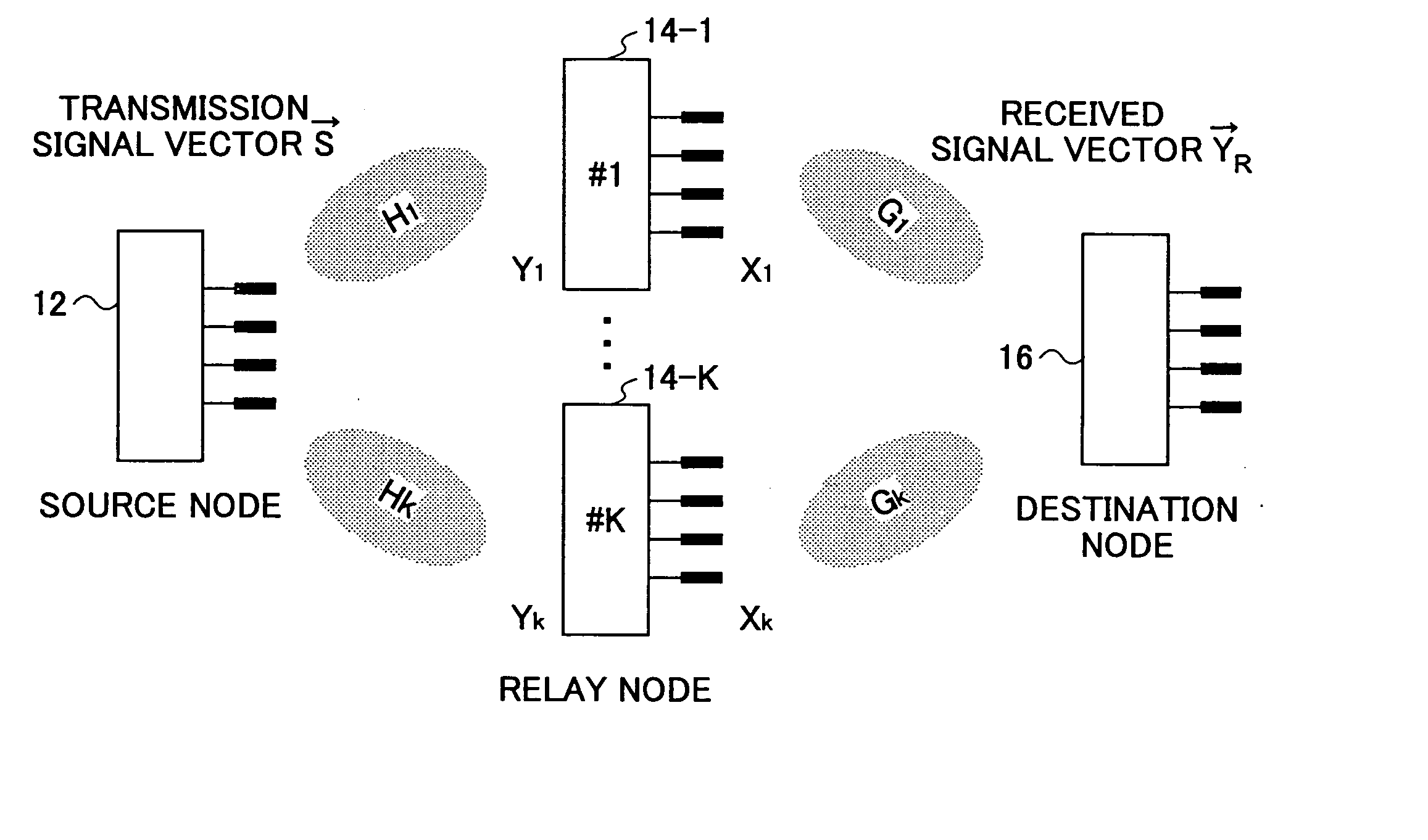
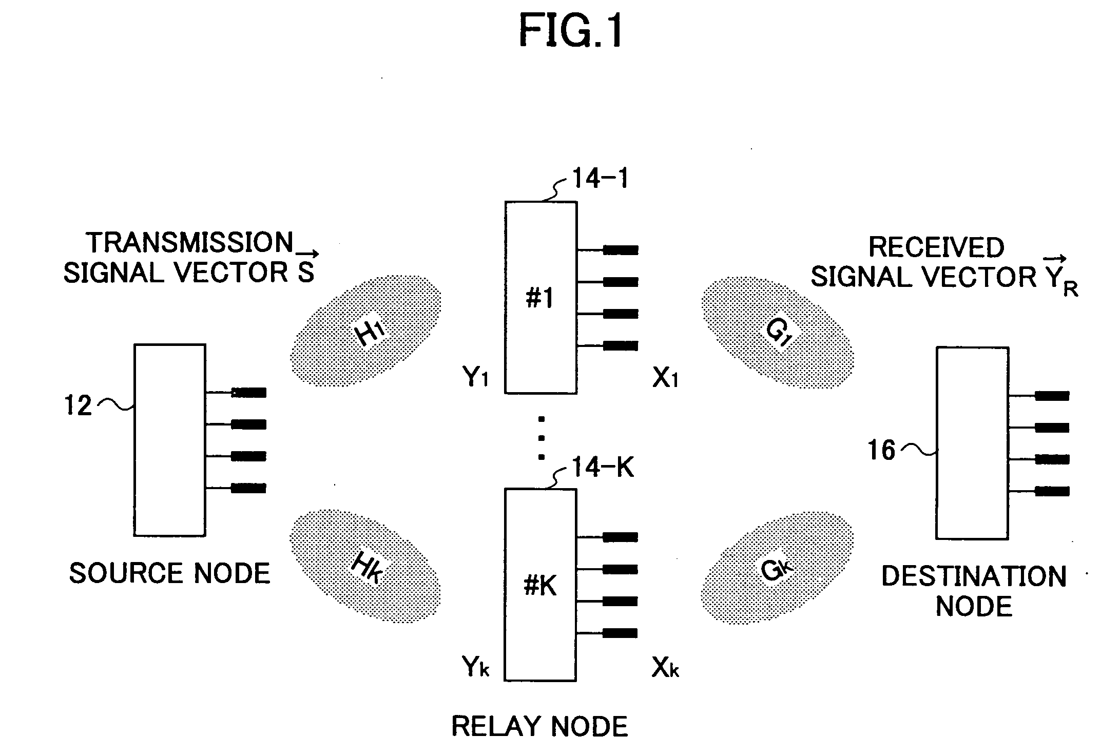
[0060]FIG. 1 is a schematic diagram illustrating the overall structure of a communication system according to an embodiment of the invention. The communication system employs a multihop scheme and a multiple-input multiple-output (MIMO) scheme. The communication system includes a source node 12, a destination node 16, and K (K≧1) relay nodes 14-1 through 14-K. The k-th relay node is denoted as 14-k (1≦k≦K). Communications between the source node 12 and the relay node 14-k and communication between the relay node 14-k and the destination node 16 are performed using a MIMO scheme. Signal transmission from the source node 12 to the destination node 16 is performed by a multihop scheme. In this embodiment, each of the K relay nodes can relay a signal from the source node 12 to the destination node 16 by one hop, for simplification purpose. However, the number of hops may be increased.
[0061] The source node 12 transmits mutually distinguishable signals from multiple antennas (M antennas...
embodiment 2
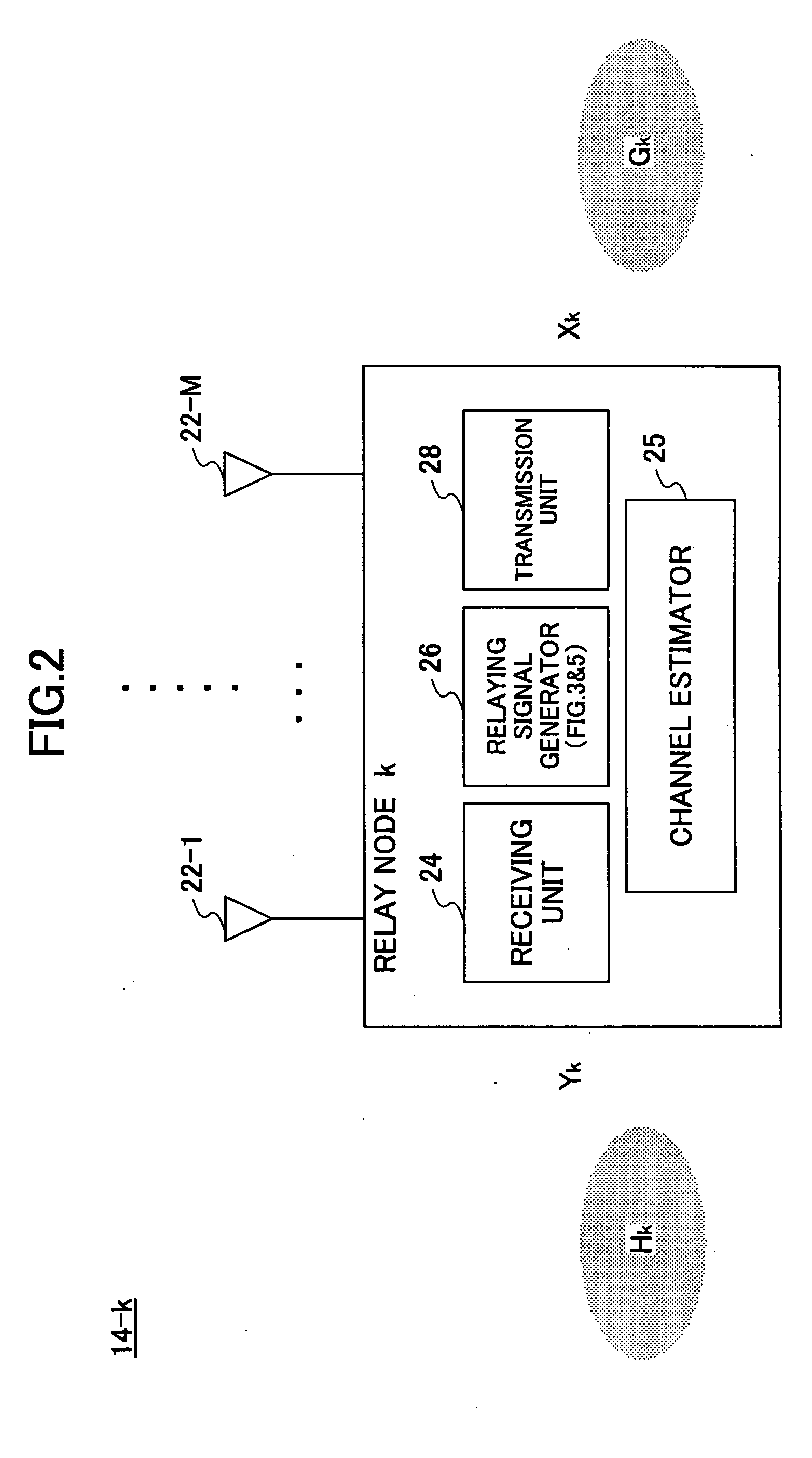
[0089]FIG. 5 is a functional block diagram of the relaying signal generator 26 used in the relay node 14 according to the second embodiment of the invention. The relaying signal generator 26 includes a QR decomposition unit 32, a weighting factor calculation unit 34, a first weighting unit 36, a signal detector 39, and a second weighting unit 62. In the second embodiment, the destination node 16 may have the structure and functions shown in FIG. 5, or alternatively, it may have the structure and functions shown in FIG. 3.
[0090] Upon receiving information about the channel matrices Hk and Gk from the channel estimator 25, the QR decomposition unit 32 breaks down the channel matrix Hk in a form of product of a unitary matrix Qk and a triangular matrix Rk (Hk=QkRk). The the QR decomposition unit 32 also breaks down the channel matrix Gk into the form of a product of a triangular matrix PkH and a unitary matrix OkH (Gk=PkHOkH).
[0091] The weighting factor calculation unit 34 calculates...
embodiment 3
[0108]FIG. 7A and FIG. 7B are graphs showing simulation results of signal transmission according to an embodiment of the invention. The horizontal axis represents power to noise ratio (PNR), and the vertical axis represents capacity. In FIG. 7A, the number of transmission antennas and the number of receiving antennas are each four, and two relay nodes (K=2) are located between the source node and the destination node within a one-hop communication range. The curve of theoretical limit indicates the theoretical limit of the capacity as a function of PNR, and the curve of the prior art indicates the capacity when relaying signals using the zero-forcing method. The curve of Embodiment 1 is obtained by implementing the method of the first embodiment. In FIG. 7B, the number of transmission antennas and the number of receiving antennas are each four, and four relay nodes (K=4) are located between the source node and the destination node within a one-hop communication range. From the graph...
PUM
 Abstract
Description
Claims
Application Information
 - R&D
- Intellectual Property
- Life Sciences
- Materials
- Tech Scout
- Unparalleled Data Quality
- Higher Quality Content
- 60% Fewer Hallucinations
Browse by: Latest US Patents, China's latest patents, Technical Efficacy Thesaurus, Application Domain, Technology Topic, Popular Technical Reports.
© 2025 PatSnap. All rights reserved.Legal|Privacy policy|Modern Slavery Act Transparency Statement|Sitemap|About US| Contact US: help@patsnap.com


