

Intradiscal production of autologous interleukin antagonist
a production method and technology of interleukin, applied in the field of intradiscal production of autologous interleukin antagonist, can solve the problems of high toxicity, retard the flow of nutrients into the disc, retard the flow of waste products out of the disc, etc., and achieve the effect of reducing inflammation and treating sciatica
- Summary
- Abstract
- Description
- Claims
- Application Information
AI Technical Summary
Benefits of technology
Problems solved by technology
Method used
Image

Examples
example i
[0056] This prophetic example describes a typical method of the present invention.
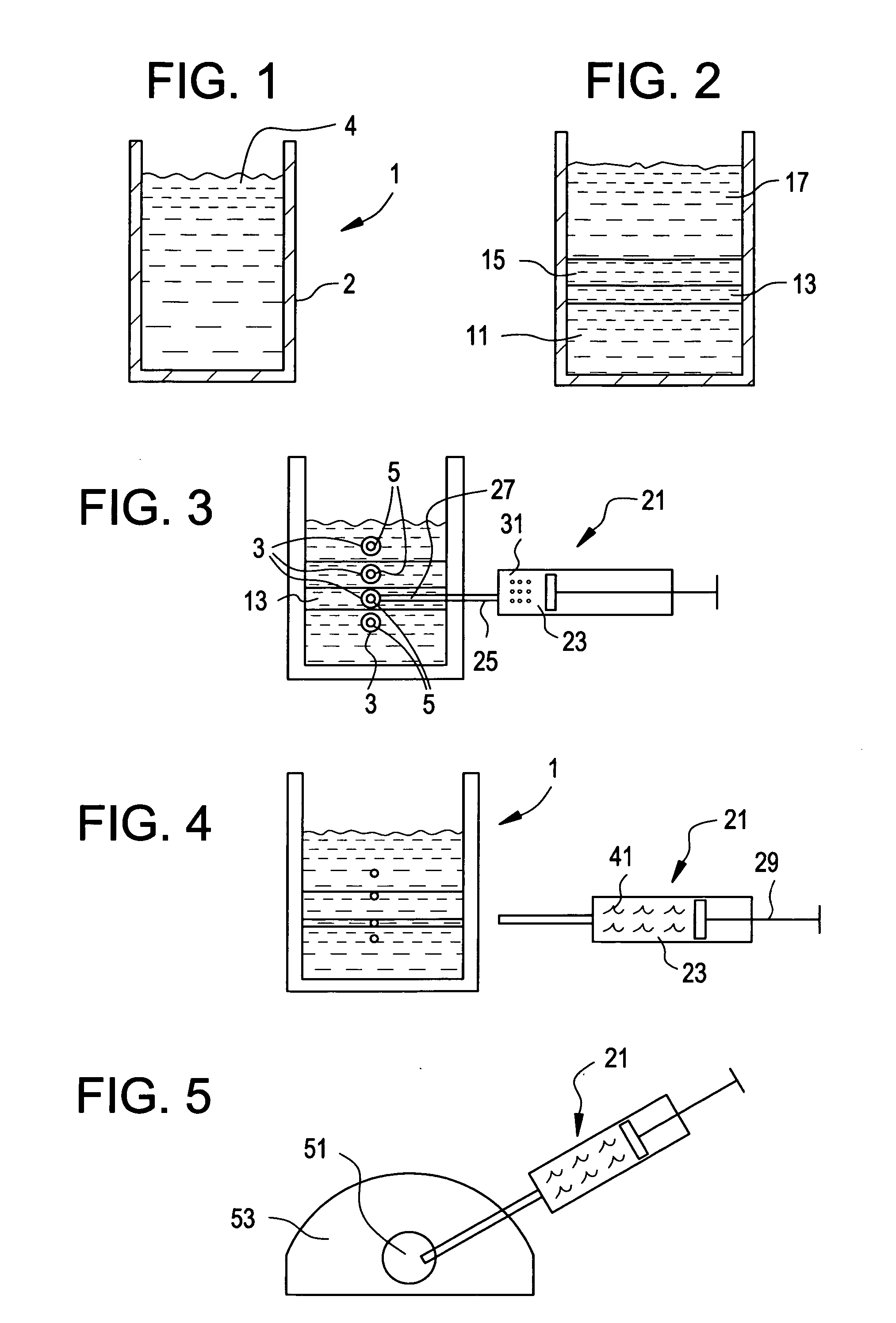
[0057] First, about 20 cc of blood is taken from the patient. Now referring to FIG. 1, the blood 4 is placed in a centrifugation container 1 adapted for centrifugation and having a side wall 2.
[0058] Now referring to FIG. 2, the blood is centrifuged to produce centrifuged blood fractions including red blood cells 11, platelets 13, buffy coat 15 and platelet poor plasma 17.
[0059] Now referring to FIG. 3, a syringe 21 having a barrel 23 containing a lyophilized immunoglobulin powder 31 and a needle 25 is provided. The centrifugation container has a plurality of side ports 3 having puncturable gaskets 5 therein. The clinician inserts the distal end 27 of the needle through the lowest gasket in the buffy coat portion 13 of the fractionated blood.
[0060] Now referring to FIG. 4, the clinician pulls back upon the plunger 29. The vacuum created by withdrawl of the plunger causes the buffy coat fluid to ent...
PUM
| Property | Measurement | Unit |
|---|---|---|
| concentration | aaaaa | aaaaa |
| concentration | aaaaa | aaaaa |
| concentration | aaaaa | aaaaa |
Abstract
Description
Claims
Application Information