
Battery pack

a battery pack and battery technology, applied in the field of batteries, can solve the problems of power loss and unsuitability of plastic materials for battery pack housings, and achieve the effects of reducing material costs, improving mechanical properties, and improving break strength

Inactive Publication Date: 2006-03-16
ROBERT BOSCH GMBH
View PDF23 Cites 25 Cited by
  • Summary
  • Abstract
  • Description
  • Claims
  • Application Information

AI Technical Summary

Benefits of technology

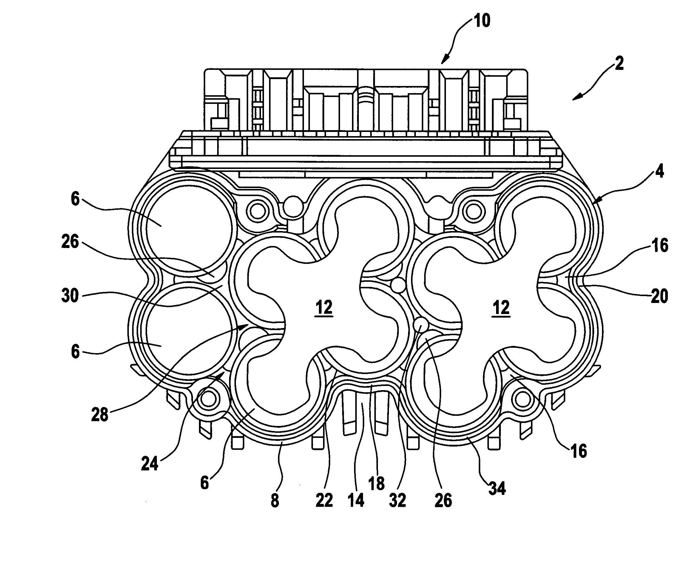
[0008] When the battery pack is designed in accordance with the present invention it offers the advantage that not only does it have an adequate thermal conductivity for dissipating even the heat generated in the housing interior by high-power batteries as well as satisfactory mechanical properties for use as a battery pack housing material. It is moreover quite inexpensive and can be manufactured using conventional molding processes.
[0009] Surprisingly, it has been found that polyethylene, which until now has been used above all as bulk plastic but used less often for high-grade technical articles, is especially suitable as material for battery pack housings, because its thermal conductivity is considerably higher than that of the conventional battery pack housing materials recited at the outset, since it is hardly worse than those in terms of most of the strength properties demanded or desired for battery packs, and it has an even greater breaking strength, and because it is furthermore extremely inexpensive.
[0011] As material for the battery pack housings of the invention, high-density polyethylene (PE-HD) is preferably used, since its mechanical properties, such as breaking strength, are better, with at the same time lower material costs, than those of high-molecular polyethylene (PE-HMW) and ultrahigh-molecular polyethylene (PE-UHMW) and are more than satisfactory for battery pack housings.
[0012] A further advantage of using high-density polyethylene, with thermal conductivity of approximately 0.4 to 0.42 W / mK, is that this thermal conductivity is approximately equivalent to the maximum thermal conductivity of the battery cell material itself. While insulating air gaps between the housing wall and the cell are avoided, this means that the risk of overheating of the cell cannot necessarily be reduced by further increasing the thermal conductivity of the housing material, because then the dissipation of the heat out of the cell represents the limiting factor, in terms of the risk of overheating, for the maximum power conversion in the cell.
[0013] For preventing insulating air gaps between the housing wall and the cells, a further preferred feature of the invention provides that an outer wall of the housing, surrounding the battery cell, rests with at least half of its inner wall surface against an adjacent circumferential face of the battery cell. Because of such a large-area contact of the circumferential face of the battery cell, or of each battery cell, with the outer housing wall, air-filled interstices between the cell or cells and the outer wall are avoided as much as possible; as a result, the heat transfer from the cell or each cell into the housing wall is improved, and thus the heat resistance between the battery cells and the environment can be reduced.
[0016] Since the scratch resistance of high-density polyethylene (PE-HD) is not quite that of the conventional battery pack housing materials mentioned at the outset, fillers in the form of powdered or chiplike substances with a particle size of less than 20 μm and preferably less than 10 μm can be added into the plastic material of the housing in the manufacture of the housing. By a suitable choice of the fillers and their proportion by weight or volume in the plastic material, the thermal conductivity of the plastic material of the housing can furthermore be increased somewhat as needed, or adapted to the thermal conductivity of the battery cells themselves, for instance by using fillers in the form of metal powders or powdered metal oxides, such as aluminum or aluminum oxides.

Problems solved by technology

However, the development of newer battery cells is moving in the direction of increasing the power conversion, making the power loss also greater, so that more heat is released in the interior of the housing and must be dissipated faster to the environment, to prevent overheating of the battery cells.
However, these plastic materials are mostly unsuited for battery pack housings, either because they lack adequate mechanical properties, or they are simply too expensive for this intended use.

Method used


Image

  • Battery pack
  • Battery pack

Examples


Embodiment Construction

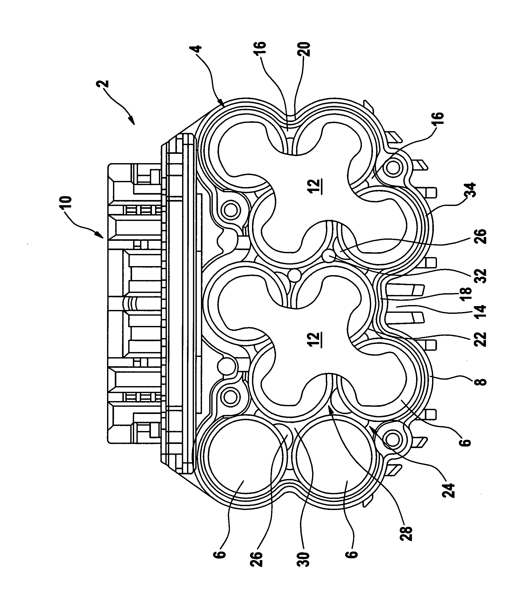
[0019] The battery pack 2 shown in the drawing serves as a power supply for an electrical appliance, such as a handheld power tool. It substantially comprises a housing 4 that is open on its upper face end, one or more layers of battery cells 6 placed side by side in the housing 4 (only the uppermost layer is visible in the drawing), and a closure (not shown), which closes the housing 4 on the face end of the uppermost layer of cells 6. The closure, as a rule formed by part of the electrical appliance, includes two contacts that come into contact with connection contacts of the battery pack 2 when the housing 4 is closed in order to connect series- or parallel-connected cells 6, accommodated in the housing 4, to a current circuit of the consumer of the electrical appliance.

[0020] The housing is produced in one piece by injection molding from high-density polyethylene (PE-HD). Besides a bottom wall (not visible) and a circumferential wall 8, it includes a locking and connection part...


PUM


Abstract

A battery pack for supplying power to an electrical appliance, in particular a power tool, has a housing which at least partly comprises plastic and holds at least one battery cell, wherein the plastic is a polyethylene (PE) with a density of more than 0.93 g / cm3

Description

BACKGROUND OF THE INVENTION [0001] The invention relates to a battery pack for supplying power to an electrical appliance. [0002] The terms battery cell and battery pack used here are also intended to include rechargeable current-storing means (accumulators) and accumulator packs. [0003] Battery packs for supplying power to electrical appliances, such as handheld power tools, typically have housings that for the most part comprise plastic materials. Plastic materials typically used for battery pack housings include acrylonitrile-butadiene-styrene (ABS), polycarbonate (PC), or polyamide (PA), such as PA6 or PA12. These plastic materials have good mechanical properties and a thermal conductivity sufficient to make them suitable for use as battery pack housings for most battery cells currently available on the market. [0004] However, the development of newer battery cells is moving in the direction of increasing the power conversion, making the power loss also greater, so that more hea...

Claims


Application Information

Patent Timeline
IPC IPC(8): H01M2/02H01M50/107H01M50/503H01M50/522
CPCH01M2/105H01M2/204H01M2/1094H01M2/1055Y02E60/10H01M50/213H01M50/24H01M50/503H01M50/107H01M50/522
Inventor MATTHIAS, WOLFREJMAN, MARCIN
Owner ROBERT BOSCH GMBH
Learn More