Components for use in large-scale concrete slab constructions

a technology of large-scale concrete and components, applied in the direction of structural elements, building components, building reinforcements, etc., can solve the problems of large, unfavorable construction safety and convenience, and large stirrups, and achieve the effect of sufficient internal tensile strength

Inactive Publication Date: 2006-03-23
BROWN WILLIAM GRANT
View PDF13 Cites 29 Cited by
  • Summary
  • Abstract
  • Description
  • Claims
  • Application Information

AI Technical Summary

Benefits of technology

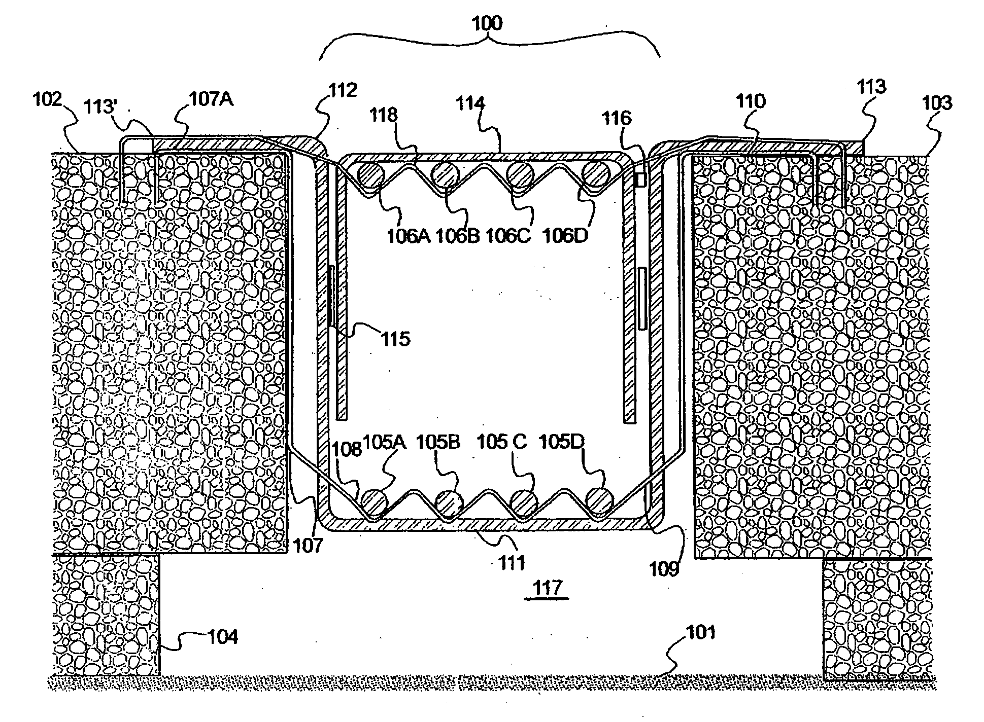
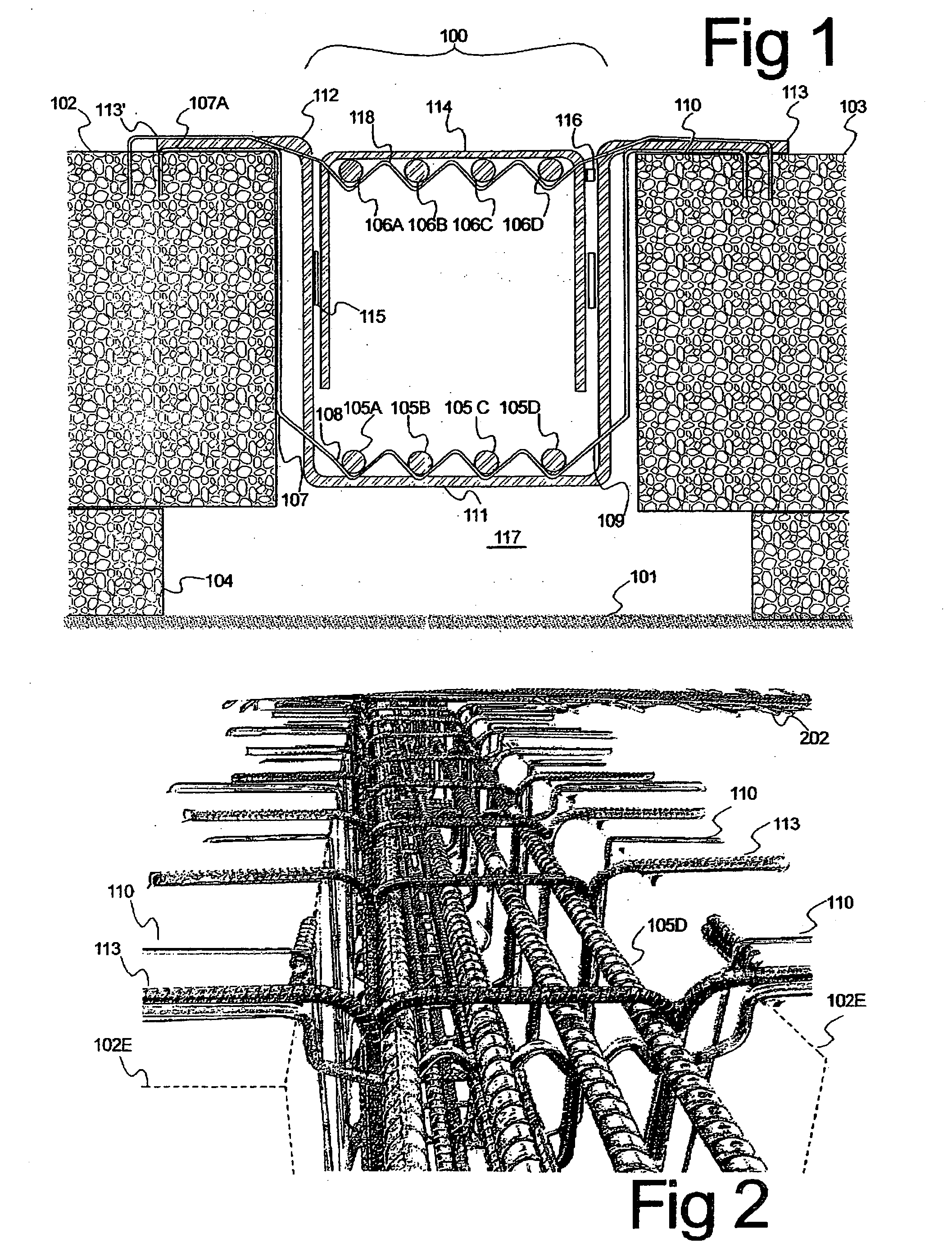
[0014] In one option, the components are used along the strengthening beams or ribs of concrete as a series of single components and each single component includes (a) more than one attachment points each for a reinforcing bar of a reinforcing structure held at a predetermined position, and (b) includes at least one attachment point for location of the component with respect to an adjacent former so that each single component is capable of holding said reinforcing bars at predetermined positions with respect to the adjacent former and (c) includes sufficient internal tensile strength to serve as a structural element of the reinforcing structure.
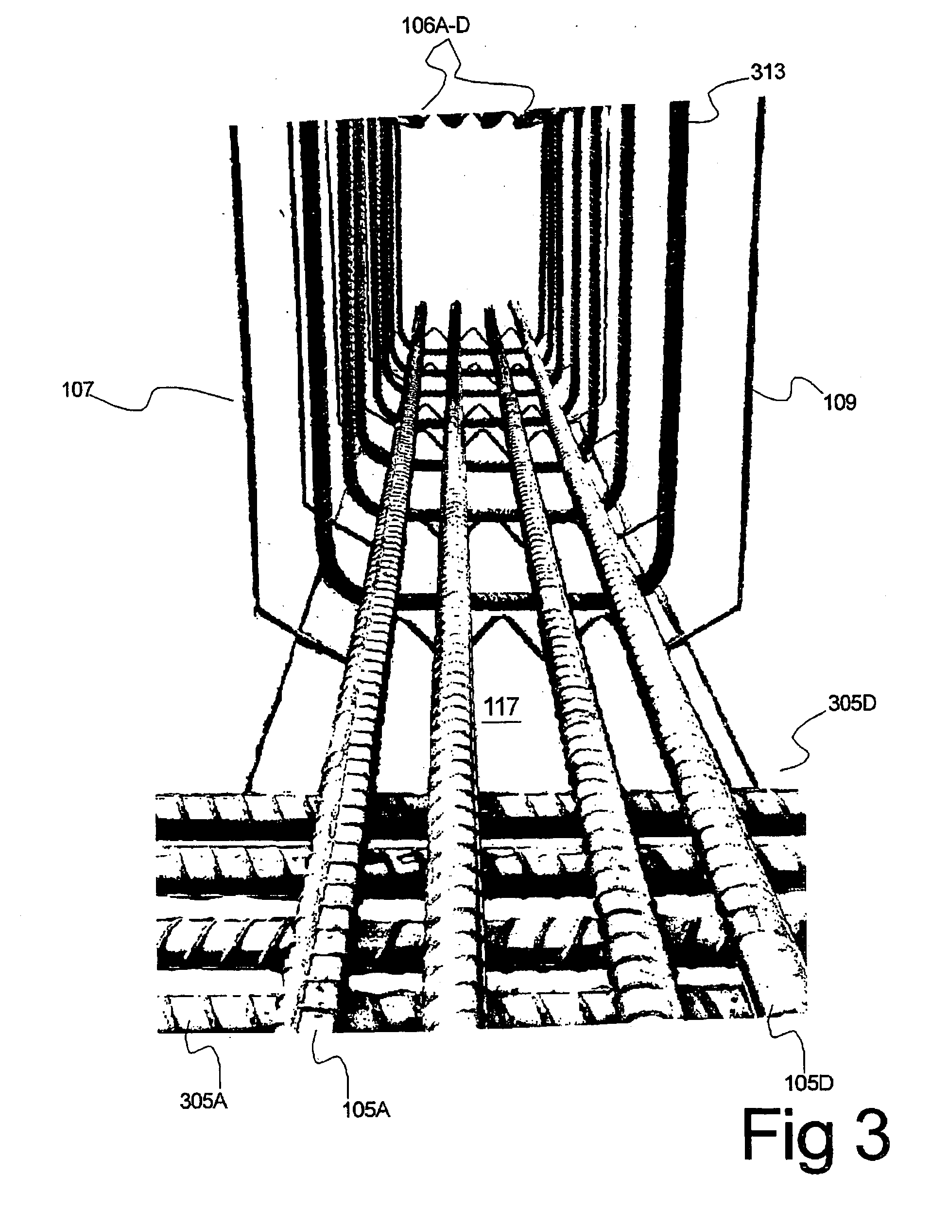
[0015] In another option, the components are used as members of a group of components used along the strengthening beams or ribs of concrete as a series of groups of components for assembly into part of the structure during construction, and each group of components after assembly includes (a) more than one attachment points for more than one reinforcing bars each held at a predetermined position, and\(b) at least one attachment point for location with respect to an adjacent former so that each single component is capable of holding said reinforcing bars at predetermined positions with respect to the adjacent former, and (c) each group of components after assembly serves as a cage assembly capable of holding said reinforcing bars at predetermined positions.
[0016] In a related aspect the invention provides a set of components for use as a group in reinforced concrete structures; the set including an upper bar support, a lower bar support and channel spacer, a lower cage stirrup, and an upper cage member; all to be used as spaced-apart sets in conjunction with reinforcing rods placed horizontally within channels.
[0017] Preferably the group comprises an “n-bar cage” where n may be from two to sixteen bars of reinforcing rods.
[0018] In a second broad aspect this invention provides a method for assembly of a group of components as previously described in this section between formers and along an intended strengthening beam or rib, including the steps of: (a) placing non-structural “pod spacers and bar organisers” along the channel in order to to locate and hold the void formers in place during later component placement, and thereby to maintain the channel width, (b) placing a structural “top hat” deep bar-holding bent wire shape with sufficient depth to support a first, lower layer of bars at the deepest level, alongside each pod spacer and bar organiser, (c) placing a deep array of structural reinforcing rods in the grooves provided by a series of pod spacers and bar organisers, (d) placing a shallow non-structural pod spacer and bar organiser, (e) placing a second, shallow array of structural reinforcing rods, (f) placing an inverted “U” structural element to serve as part of the cage over the shallow array of reinforcing rods, and then (g) fixing the structural elements to each other such as by tying or welding, so that the assembly is ready for receiving wet concrete and providing reinforcement once the concrete has cured.
[0019] Preferably the respective arrays of reinforcing rods are installed so as to cross over each other at positions where beams of reinforced concrete are intended to intersect, thereby creating interlocking reinforcing cage assemblies at the site.

Problems solved by technology

After the reactions involved in setting and curing have taken place it has good compressive strength but relatively poor tensile and shear strength, so rods of reinforcing iron are cast into masses of concrete in order to restore tensile and shear strength.
Use of these stirrups sharply reduces the labour content of a floor.
Problems associated with this technique include the matter of creating cage structures of just the right size (let alone possible distortion during transport and placement) and of moving the heavy, large, and not particularly strong structures safely and conveniently to their final positions.

Method used


Image

  • Components for use in large-scale concrete slab constructions
  • Components for use in large-scale concrete slab constructions
  • Components for use in large-scale concrete slab constructions

Examples


example 1

Structural Stirrups

[0035] Structural stirrups, also known as structural spacers because they space apart bars and void formers (or other formwork), provide extra points for locating lengths of reinforcing iron within a channel so that the resulting rib will have a structurally useful degree of strength. Examples are shown as FIGS. 4, 6, 7 and 8. They include bends to locate bars of reinforcing iron at a range of depths. The structural stirrup of FIG. 4 includes downward-directed bends at 409, 401 and 415 that can hold bars by gravity alone, avoiding the labour costs of placing wire ties. Extra bars could be tied in at 407 and 408, providing either a three-bar reinforced rib, or a five-bar reinforced rib.

[0036]FIG. 4 shows a typical structural component, according to the invention, for use in reinforced concrete structures. (Dimensions are given by way of illustration only). This component is made of 6.4 mm diameter steel rod, formed by bending in a numerically controlled bending a...

example 2

Cage Constructions, Assembled on the Site

[0050] A further development of the present invention that is intended for significantly greater loadings is partly based on a non-structural stirrup as per FIG. 5a, but with additional parts. Further, it resembles a cage structure, but one that is preferably assembled on site. Some functions of a simple stirrup, such as determination of the channel size are retained. By way of comparison, we first describe a prior-art four-bar cage structure illustrated as FIG. 5b. In this cage, which has an indefinite length, four bars such as 502, 504, 505 and 506 are tied to a series of bent reinforcing iron bars 503 which serves to maintain the bars in a spaced-apart configuration after embedment in concrete, so that the resulting reinforcement has greater strength to resist torques. Larger cages would use stouter rods and have more of them.

[0051] This description and these drawings are based on a specific prototype, show an eight-bar cage, and refer t...


PUM


Abstract

Structural reinforcing members are supplied for use in resisting shear forces within larger construction projects using reinforced concrete, along sites where strengthening ribs or beams between formers are to be created. The members also force the channels apart and maintain the reinforcing therein before curing at predetermined dimensions and spacings. A variant provides reinforcing cages that can be put together on the site for maintaining multiple reinforcing rods. The cages of different beams can intermesh at rib cross-over points. Example cages are eight-bar cages where each bar is made of 1.25 inch diameter reinforcing steel. During assembly the bars are held in place by the members with the assistance of gravity so that relatively little linking together of the reinforcing parts is required.

Description

FIELD [0001] This invention relates to building construction, to the provision of reinforcement for concrete structures, and in particular to structural components for incorporation in reinforced concrete masses to become built structures such as floors, buildings, bridges, or roads. BACKGROUND [0002] Concrete is a widely used cold-castable “liquid stone” used as a building material. After the reactions involved in setting and curing have taken place it has good compressive strength but relatively poor tensile and shear strength, so rods of reinforcing iron are cast into masses of concrete in order to restore tensile and shear strength. For use in mainly single-storey domestic housing floors poured as single slabs, the inventor has previously described a floor construction technique using buried void formers (made from a foam plastics such as polystyrene foam) to form a matrix of stiffening beams in the spaces left between the formers, using the inventor's stirrups to place reinforc...

Claims


Application Information

Patent Timeline
Patent Type & Authority Applications(United States)
IPC IPC(8): E04C5/08
CPCE04C5/0604E04C5/168E04C5/0645
Inventor BROWN, WILLIAM GRANT
Owner BROWN WILLIAM GRANT
Why Eureka
Try Eureka