Effervescence injector for an aero-mechanical system for injecting air/fuel mixture into a turbomachine combustion chamber

Active Publication Date: 2006-03-23
SN DETUDE & DE CONSTR DE MOTEURS DAVIATION S N E C M A
View PDF6 Cites 44 Cited by
  • Summary
  • Abstract
  • Description
  • Claims
  • Application Information

AI Technical Summary

Benefits of technology

[0009] A main object of the present invention is thus to mitigate such drawbacks by proposing an injector for an aero-mechanical injection s

Problems solved by technology

Aero-mechanical injection systems known in the prior art present numerous drawbacks.
In particular, the pressure limitation does not enable the size of fuel dr

Method used


Image

  • Effervescence injector for an aero-mechanical system for injecting air/fuel mixture into a turbomachine combustion chamber
  • Effervescence injector for an aero-mechanical system for injecting air/fuel mixture into a turbomachine combustion chamber
  • Effervescence injector for an aero-mechanical system for injecting air/fuel mixture into a turbomachine combustion chamber

Examples


Embodiment Construction

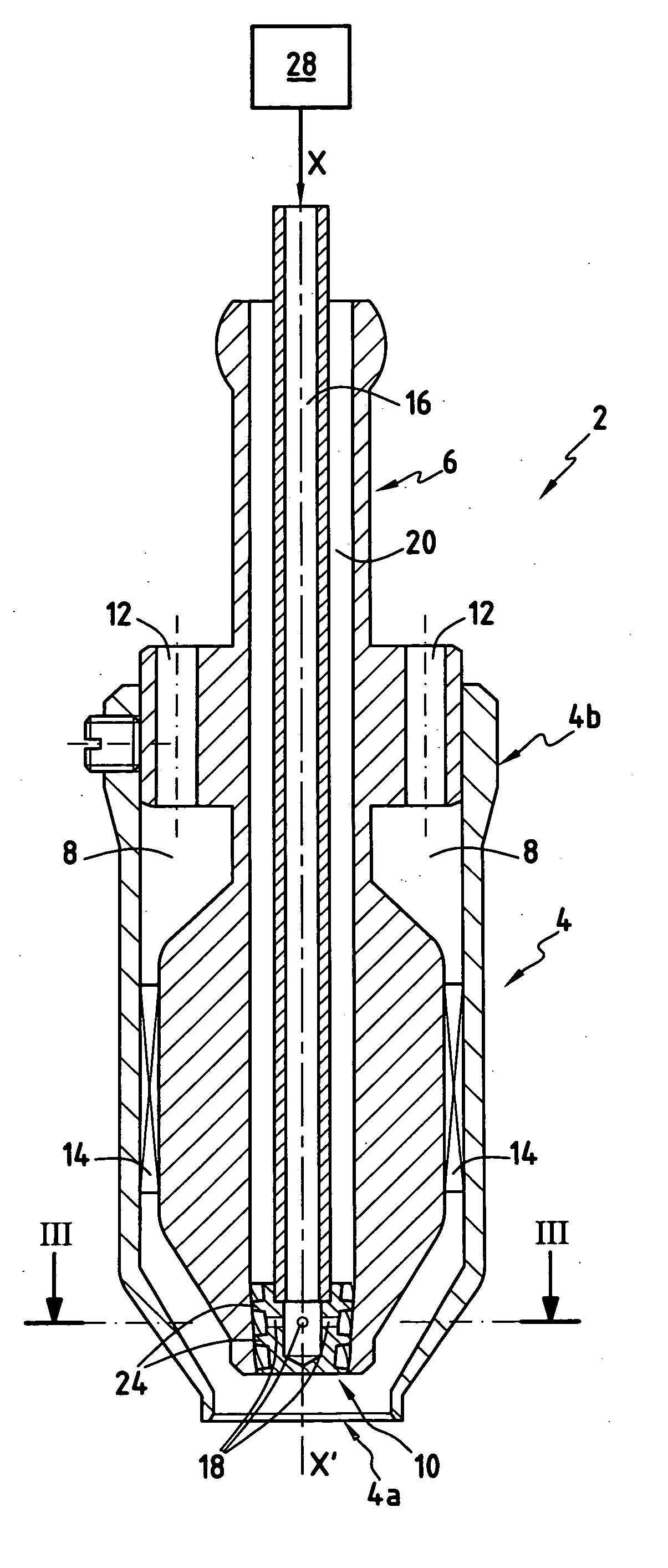
[0029] With reference to FIGS. 1 and 4, the fuel injector 2, 2′ of the invention is generally in the form of a main tubular structure 4 about an axis XX′ that opens out at a downstream end 4a for delivering the air / fuel mixture. The downstream end 4a of the tubular structure 4 may be substantially conical in shape.

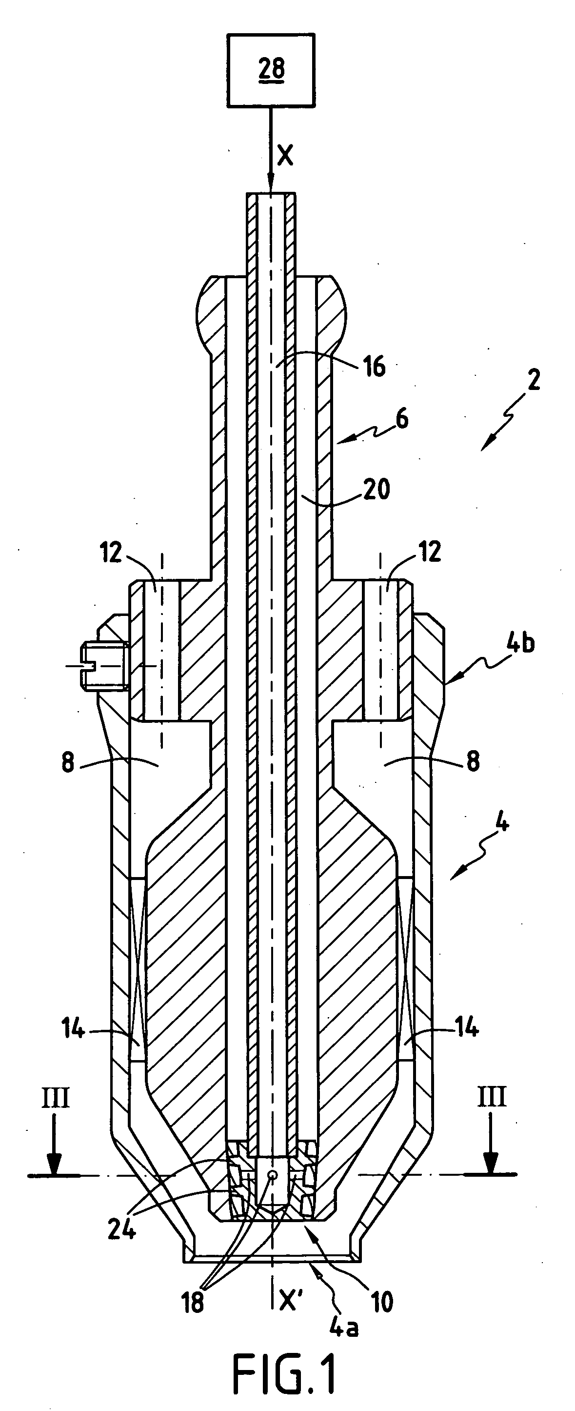
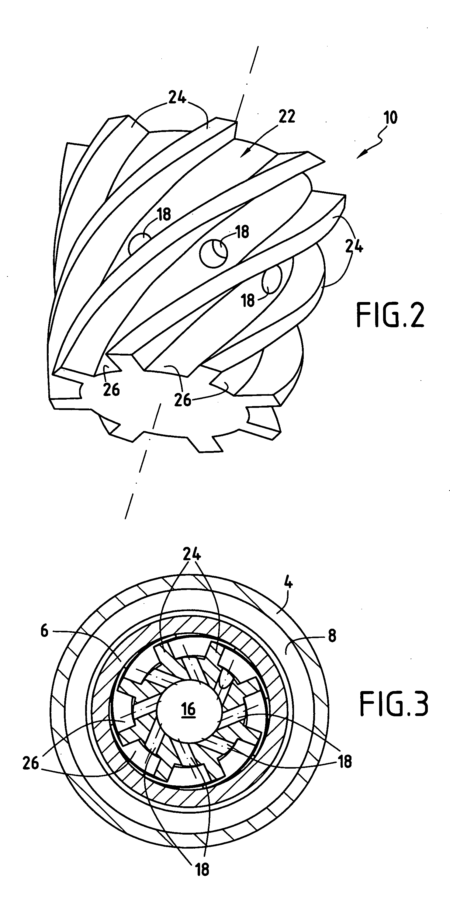
[0030] A tubular fuel duct 6 is disposed inside the main structure 4 so as to co-operate therewith to form an annular passage 8. The tubular duct 6 which is centered on the axis XX′ opens out at a downstream end inside the main structure 4 via a fuel atomizer plug 10, 10′. Its downstream end may also be substantially conical in shape.

[0031] The fuel atomizer plug 10, 10′ serves to introduce fuel at a pressure PC, e.g. of about 4 bar to 80 bar, into the main structure 4 at its downstream end 4a. Its main function is to cause the fuel to be dispersed in the form of a plurality of jets (or tubes) of fuel.

[0032] The fuel injector 2, 2′ further comprises at least one air fee...


PUM


Abstract

A fuel injector for an aero-mechanical injection system for injecting an air/fuel mixture into a turbomachine combustion chamber, the injector comprising a main tubular structure of axis XX′ opening out at a downstream end for delivering the air/fuel mixture, a tubular fuel duct that is disposed inside the main structure and that opens out into the main structure via a fuel atomizer plug so as to introduce fuel into the main structure at a pressure PC into the main structure, at least one air feed channel that opens out into the main structure so as to introduce air at a pressure PA therein, and means for injecting into the fuel duct a gas at a pressure PG that is greater than PA and greater than or equal to PC so as to create effervescence in the fuel on being introduced into the main structure.

Description

BACKGROUND OF THE INVENTION [0001] The present invention relates to the general field of systems for injecting an air / fuel mixture into a turbomachine combustion chamber. It relates more particularly to a fuel injector for an injection system of the aero-mechanical type provided with means for atomizing the fuel prior to mixing with air. [0002] The conventional process for designing and optimizing a turbomachine combustion chamber seeks mainly to reconcile implementing the operational performance of the chamber (combustion efficiency, stability domain, ignition and re-ignition domain, lifetime of the combustion area, etc.) as a function of the intended mission for the airplane on which the turbomachine is mounted, while minimizing emissions of pollution (nitrogen oxides, carbon monoxide, unburnt hydrocarbons, etc.). To do this, it is possible in particular to act on the nature and the performance of the injection system for injecting the air / fuel mixture into the combustion chamber,...

Claims


Application Information

Patent Timeline
IPC IPC(8): F02C7/22
CPCF23D11/24F23R3/30F23R3/286
Inventor FURLETOV, VICTOR IVANOVICHNOEL, THOMAS OLIVIER MARIEROLLIN, GILLES LOUISVASILEV, ALEXANDER JUREVICHYAGODKIN, VICTOR IVANOVICH
Owner SN DETUDE & DE CONSTR DE MOTEURS DAVIATION S N E C M A
Why Eureka
Try Eureka