
Process for preparing a workpiece to be worked with a laser beam, and device for carrying out the process

a technology of laser beam and workpiece, which is applied in the direction of manufacturing tools, welding/soldering/cutting articles, instruments, etc., can solve the problems of complex and expensive production of specialized devices, dynamic positioning problems, etc., and achieves less material consumption and costliness, improved weld seam formation, and less process steps.

Inactive Publication Date: 2006-03-23
DAIMLER AG
View PDF2 Cites 34 Cited by
  • Summary
  • Abstract
  • Description
  • Claims
  • Application Information

AI Technical Summary

Benefits of technology

The present invention provides a process and device for pre-treating a workpiece with a laser beam to improve weld seam formation with fewer material consumption and costliness. The process involves producing rises on one surface of the workpiece using the laser beam, which can be coordinated with the movement of the workpiece and laser beam. The device includes a transport device for positioning the workpiece and a laser beam device with a programmable processing optical assembly. The process can be carried out in various ways, such as using a fixed or moving transport device, and can be used in automobile body fabrication. The invention allows for improved weld seam formation and cost savings.

Problems solved by technology

This deformation of a workpiece in advance of welding is produced by specialized devices, which are complex and expensive.
If a deformation device and a welding device are combined into one piece of equipment, then this brings about limitations with regard to space requirement, and due to the weight, there are dynamic positioning problems, particularly if the device is to be mounted adjacent accompanying clamping devices on the arm of a robot.

Method used


Image

  • Process for preparing a workpiece to be worked with a laser beam, and device for carrying out the process
  • Process for preparing a workpiece to be worked with a laser beam, and device for carrying out the process
  • Process for preparing a workpiece to be worked with a laser beam, and device for carrying out the process

Examples


Embodiment Construction

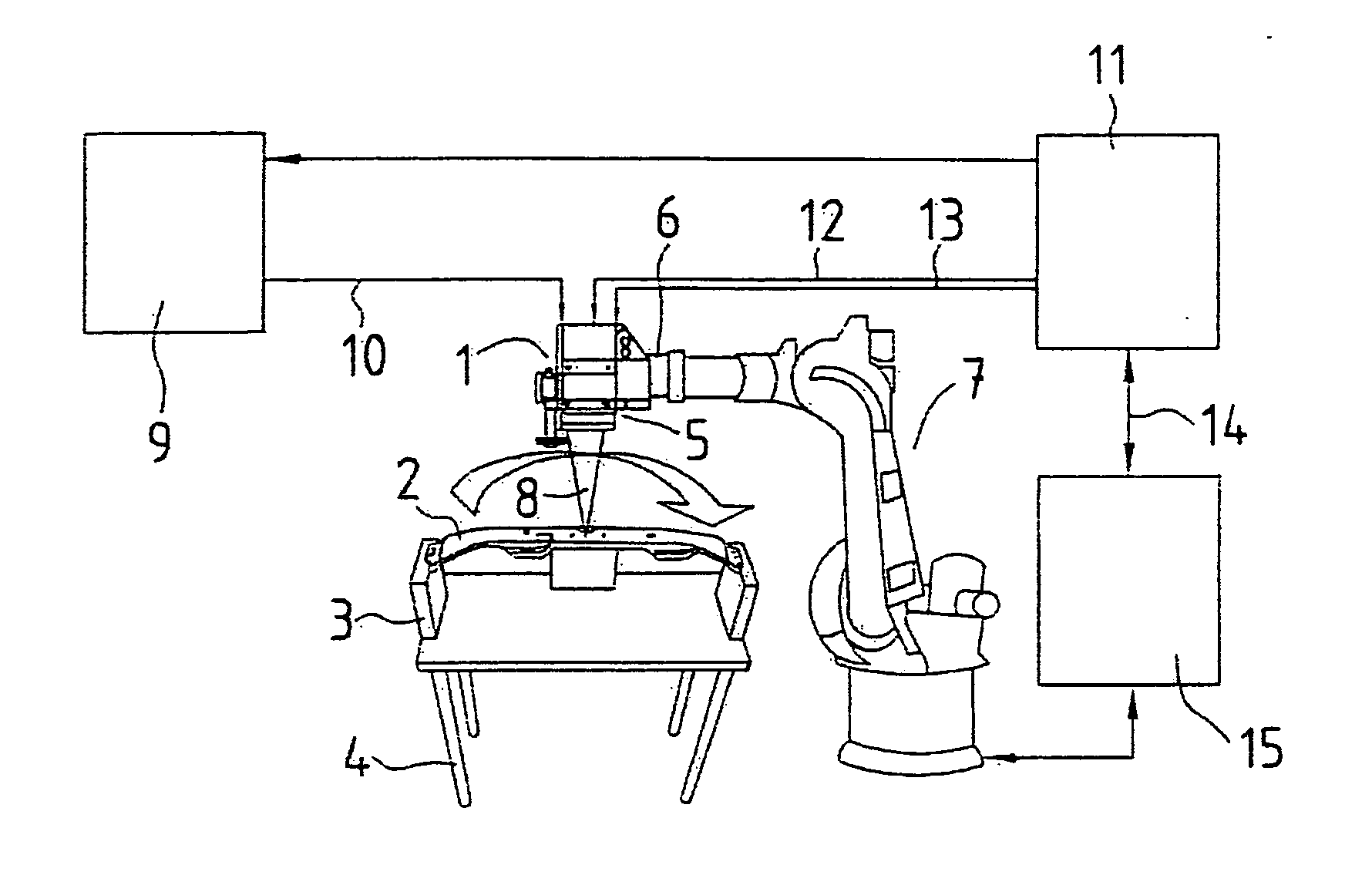
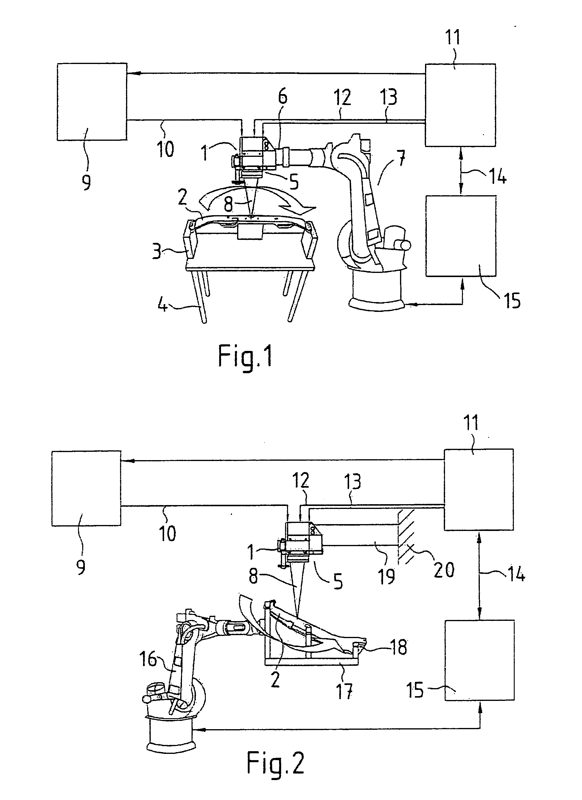
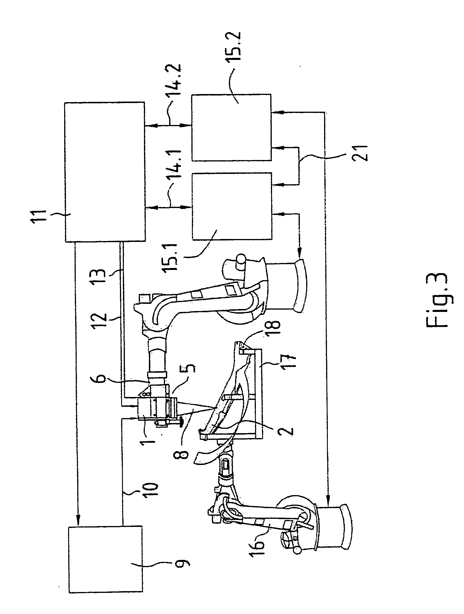
[0049] In FIG. 1 there is shown in schematic representation a sequence with moved processing optical assembly 1 and locationally fixed component 2. A robot serving as transport device picks up, with a suitable component gripper, the component 2 upon which knurls are to be formed and deposits it positionally correct in a device 3, which is secured to a frame 4. The side of a component 2 upon which knurls are to be formed faces upward for production of surface knurls. The space above the area of the component 2 to be provided with knurls and having joining flanges is freely accessible for the processing optical assembly 1. The processing optical assembly 1 is a component of a laser processing head 5, which is secured to a flange 6 of a robot 7. The position of the component 2 is fixed in the clamping fingers of the device 3. The clamping forces of the component 2 lie in the range of 100N. The clamping fingers are located spaced apart by approximately 300 mm along the joining surface. ...


PUM

PropertyMeasurementUnit
distanceaaaaaaaaaa
clamping forcesaaaaaaaaaa
distanceaaaaaaaaaa

Abstract

The invention concerns a process for pretreatment of a workpiece to be processed with a laser beam, as well as a device for carrying out the process. It is the task of the invention to develop a process and a device, which with small expenditure of material and expense, and with few process steps, makes possible an improved weld seam formation for joining workpieces. The invention is comprised therein, that for the pretreatment of a workpiece to be treated with a laser beam, in which on at least one surface of the workpiece with application of a thermal effect of at least one laser beam emitted by a laser source, rises such as knurls are formed, for the positionally correct and undistorted formation of the rises the time and spatial sequence of a relative movement between workpiece and laser beam and the output over time of the laser source are coordinated to each other via a control computer.

Description

BACKGROUND OF THE INVENTION [0001] 1. Field of the Invention [0002] In the laser welding of overlapping corrosion protection coated steel sheets (galvanized sheets), a vaporization of the coating material can occur, which leads to weld failures. For example, in the case of zinced sheets, zinc can explosively vaporize, so that weld splatters result, which reduces the quality of the weld seam. Thus, sheets are so deformed prior to welding, that free space is produced, through which the vapors can rapidly escape. [0003] 2. Related Art of the Invention [0004] DE 39 33 408 A1 discloses the lap or web welding of linked sheets is disclosed, in which the sheets are kept spaced apart by knurls or crimps, with the knurls or crimps running next to the laser weld seam. Between the knurls or, as the case may be, beads or crimps, there are free spaces, which form channels for the zinc evaporated during welding. [0005] DE 199 43 752 C1 discloses a joint location or point for laser welded component...

Claims


Application Information

Patent Timeline
Patent Type & Authority Applications(United States)
IPC IPC(8): B23K26/20B23K26/00
CPCB23K26/0884B23K26/421B23K26/3293B23K26/3206B23K26/32B23K26/60B23K2101/34B23K2103/04B23K2103/08B23K2103/50
Inventor BECKER, WOLFGANGBERNHARDT, RALFGOTH, KLAUSPAELMER, MIKEREINIGER, CLAUS-DIETERSTAHS, THOMAS G.ZAUNER, DANIEL
Owner DAIMLER AG
Learn More