
Power converter controlling apparatus and method applying a fault protection scheme in a motor drive system

a technology of fault protection scheme and control apparatus, applied in the direction of electric controllers, dynamo-electric converter control, instruments, etc., can solve the problems of motor rotor deceleration, unreliable rotor position sensors, and difficult mounting of rotor position sensors to the motor

Inactive Publication Date: 2006-03-23
HONEYWELL INT INC
View PDF18 Cites 37 Cited by
  • Summary
  • Abstract
  • Description
  • Claims
  • Application Information

AI Technical Summary

Benefits of technology

[0008] In one respect, the present invention is a method of controlling a power converter of a motor drive system, the method comprising: controlling the power converter during a first operating mode by applying a current loop control scheme, which sets power converter commands to control active and reactive current flowing from the power converter to the motor to achieve desired motor speed; and executing a fault protection scheme during a second operating mode, the fault protection scheme generating power converter commands to reduce the active current component flowing from the power converter to the motor to substantially zero.
[0009] In another respect, the present invention is a power conver

Problems solved by technology

Rotor position sensors, however, can be unreliable due to mechanism alignment and temperature incompatibility problems.
Moreover, the rotor position sensors can be difficult to mount to the motor during motor assembly, especially for multi-pole motors.
Typically, electrical contactors between the power converter and the motor are opened and IGBT gating is disabled upon detecting such non-critical fault conditions, thereby causing the motor rotor to decelerate.
In a speed sensorless system, system operation is necessary to derive motor position / speed information, which makes it difficult to achieve fault tolerance control and flying run operations.
Because such systems will lose rotor position information, it is difficult to achieve resynchronization after a temporary shut down.

Method used


Image

  • Power converter controlling apparatus and method applying a fault protection scheme in a motor drive system
  • Power converter controlling apparatus and method applying a fault protection scheme in a motor drive system
  • Power converter controlling apparatus and method applying a fault protection scheme in a motor drive system

Examples


Embodiment Construction

[0015] Embodiments of the present invention are more specifically set forth in the following description, with reference to the appended drawings. In the following description and accompanying drawings like elements are denoted with similar reference numbers. Further, well-known elements and related explanations are omitted so as not to obscure the inventive concepts presented herein.

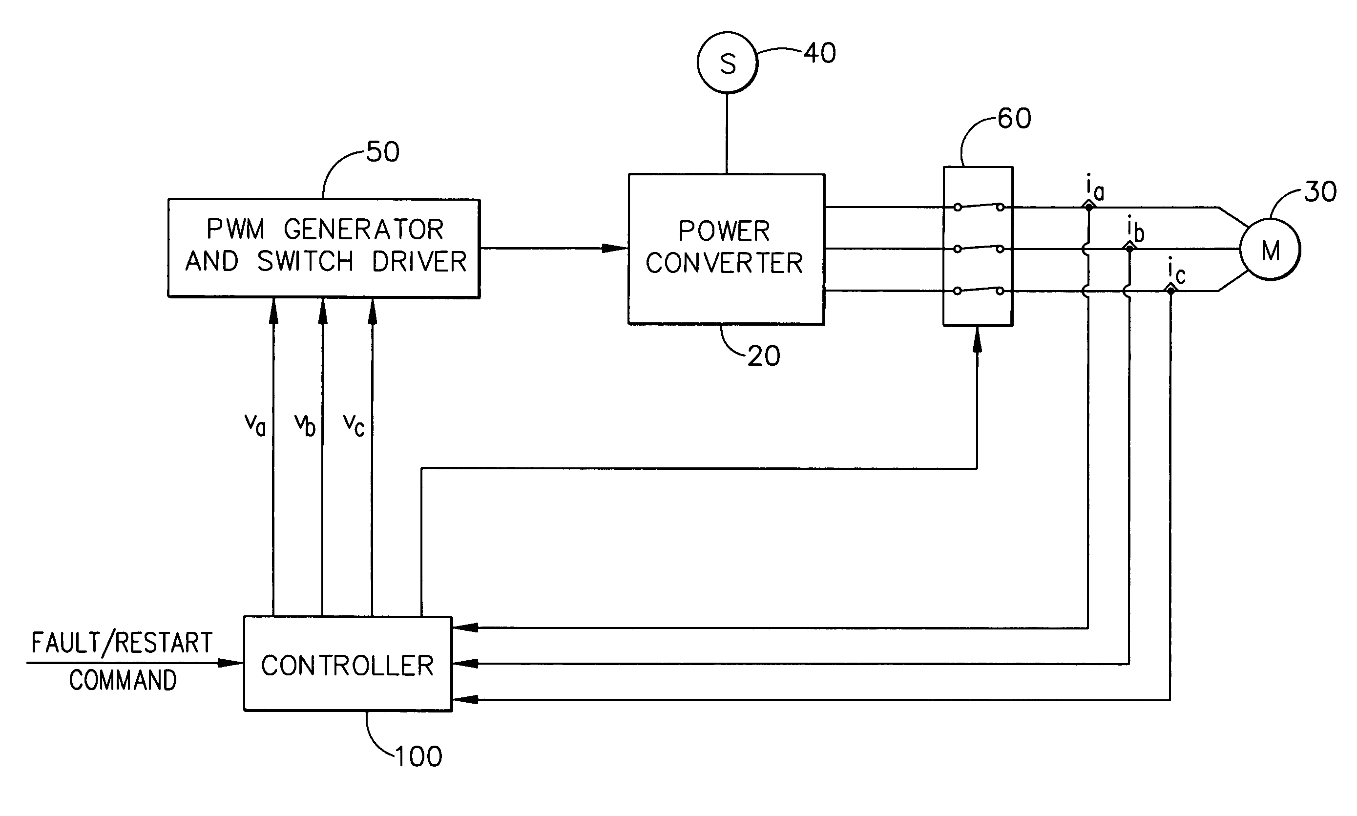
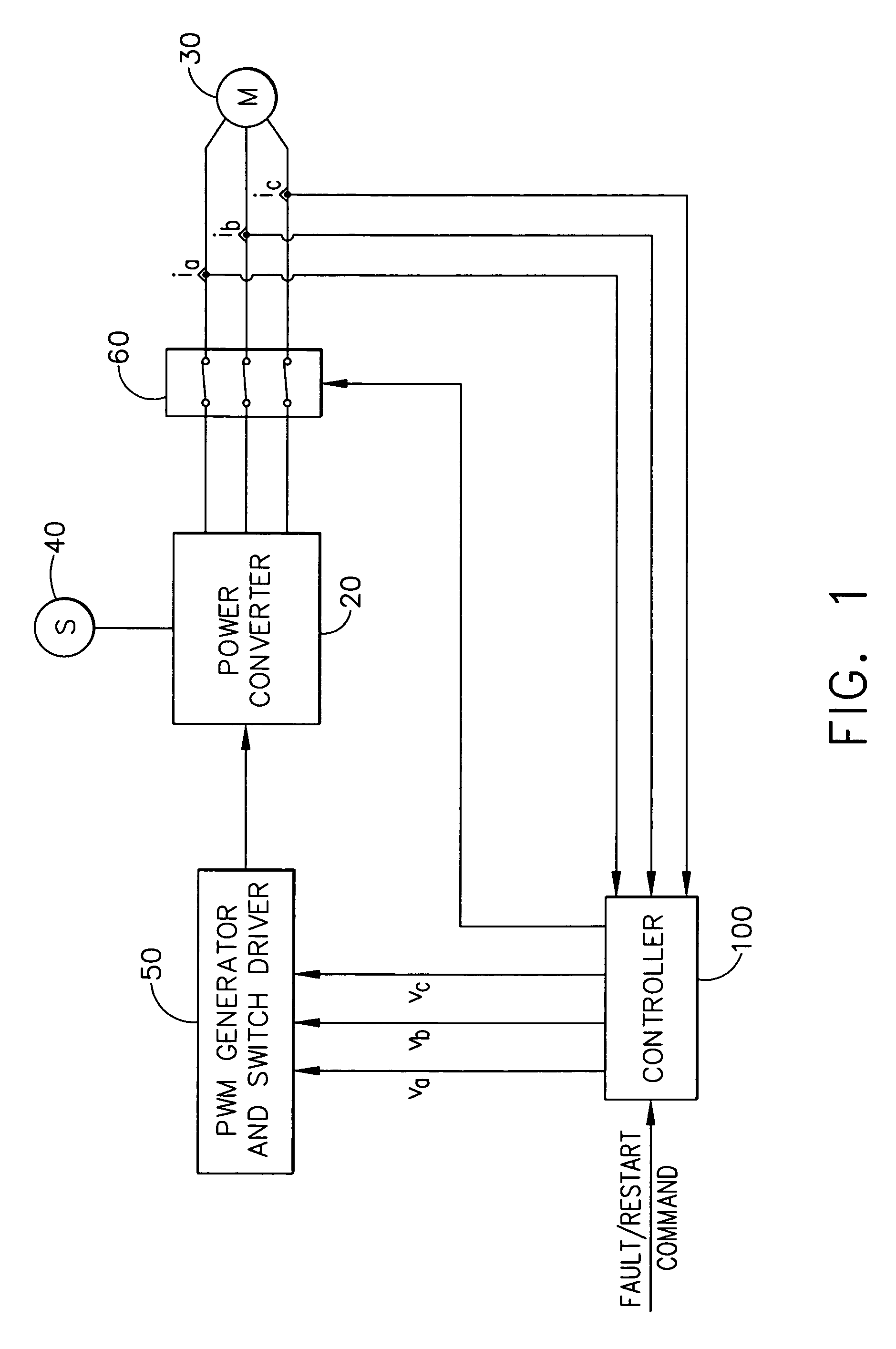
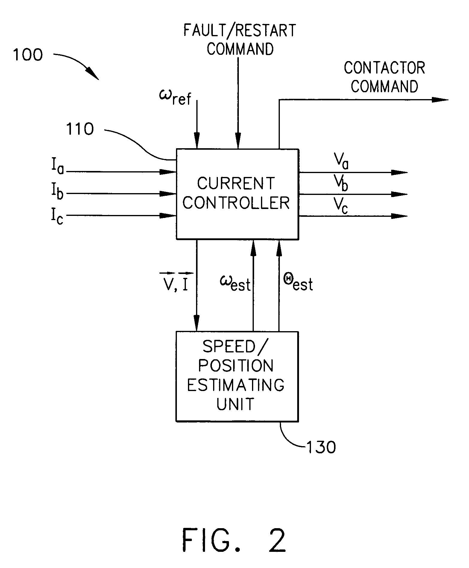
[0016] As described in detail below, the present invention provides power conversion control in a motor drive system that achieves effective fault protection by selectively reducing active current flowing between the converter and the motor to substantially zero. In one implementation, this maintains motor synchronization during fault protection mode and facilitates a flying run restart.

[0017] U.S. application Ser. No. 10 / 862,960 (“the '960 application”) titled “Instantaneous Power Floating Frame Controller,” is incorporated herein by reference in its entirety. The '960 application discloses a speed s...


PUM


Abstract

A method and apparatus control a power converter (20) of a motor drive system. The power converter (20) is controlled during a first operating mode by applying a current control scheme, which sets power converter commands to control active and reactive current components flowing from the power converter (20) to the motor (10) to achieve desired motor speed; and a fault protection scheme is executed during a second operating mode. The fault protection scheme generates power converter commands to reduce the active current component flowing from the power converter (20) to the motor (10) is substantially zero. The first operating mode will be resumed upon receiving the restart command if the motor speed is above a pre-set shutdown threshold.

Description

FIELD OF THE INVENTION [0001] The present invention relates to electrical power conversion, and more particularly to a power converter controller, and a power converter control method, applying a fault protection scheme in a motor drive system. BACKGROUND OF THE INVENTION [0002] An exemplary motor drive system includes the following main components: a synchronous motor, such as a three-phase permanent magnet synchronous motor (PMSM); a multi-phase power converter; a DC power source; a PWM (Pulse Width Modulation) Generator and switch driver; and a controller. The power converter is typically an inverter that converts DC power from power source into three-phase AC power, e.g., utilizing a configuration of insulated-gate bipolar transistors (IGBTs) under control of the PWM Generator and switch driver (pulse width modulation (PWM) control). [0003] The controller controls the power inverter via the PWM Generator and switch driver so that the power converter outputs the desired multi-pha...

Claims


Application Information

Patent Timeline
IPC IPC(8): H02H7/08
CPCH02P29/02
Inventor WANG, ZHENGMA, JACK DAMINGZHOU, GEORGE YOU
Owner HONEYWELL INT INC
Features
  • Generate Ideas
  • Intellectual Property
  • Life Sciences
  • Materials
  • Tech Scout
  • Unparalleled Data Quality
  • Higher Quality Content
  • 60% Fewer Hallucinations
Learn More