
Temperature measure device

a technology of temperature measurement and probe, which is applied in the direction of measurement devices, heat measurement, instruments, etc., can solve the problems of high cost of the device, many different probes that are somewhat labor-intensive, and the ease of manufacturing the probe, so as to reduce the cost of the device and the end user's home or professional environment, the effect of easy assembly of the cover and low cos

Inactive Publication Date: 2006-03-23
CONFORTI CARL J
View PDF13 Cites 18 Cited by
  • Summary
  • Abstract
  • Description
  • Claims
  • Application Information

AI Technical Summary

Benefits of technology

[0012] The dispensing device has a mounting member to readily attach the covers, in the manufacturing assembly or by the consumer. The covers would typically be flat, narrow and thin for low cost of manufacture and compact storage. The cartridge or dispensing unit is lightweight, typically made of plastic or like material to provide a low cost disposable carrier. A small ratchet mechanism may provide the means to dispense the probe cover and a retaining cap that can pivot about an axis, or in a linear motion, over the end of the probe that would securely fix the probe cover material onto the probe and or sensor. The material dispensed would be readily available for use.
[0013] Embodiments of the invention may also include one or more of the following features. A cartridge like dispensing unit that includes a long, thin narrow material that can be stretched onto the probe sensing device and preferably indexed to make the ease of assembly less time consuming. The index means would have a color variation or perforated edge to visually locate the dispensed unit. A guide can be adapted to the temperature measuring device housing that would include a cutting edge to tear away the disposable cover after use. Yet another feature of the invention would provide a light emitting diode or like that would provide a means to take temperature in low illuminated areas. The LED or light can be positioned at the probe area or facing towards the probe to allow the user to guide the tip for faster temperature measure in the dark.

Problems solved by technology

There are many different probes that are somewhat labor intensive to install on the temperature sensing probe or thermometer housing.
There is also an issue with the ease of manufacturing the probes and the cost of the device that makes it expensive for the end user in a home or professional environment.

Method used


Image

  • Temperature measure device
  • Temperature measure device
  • Temperature measure device

Examples


Embodiment Construction

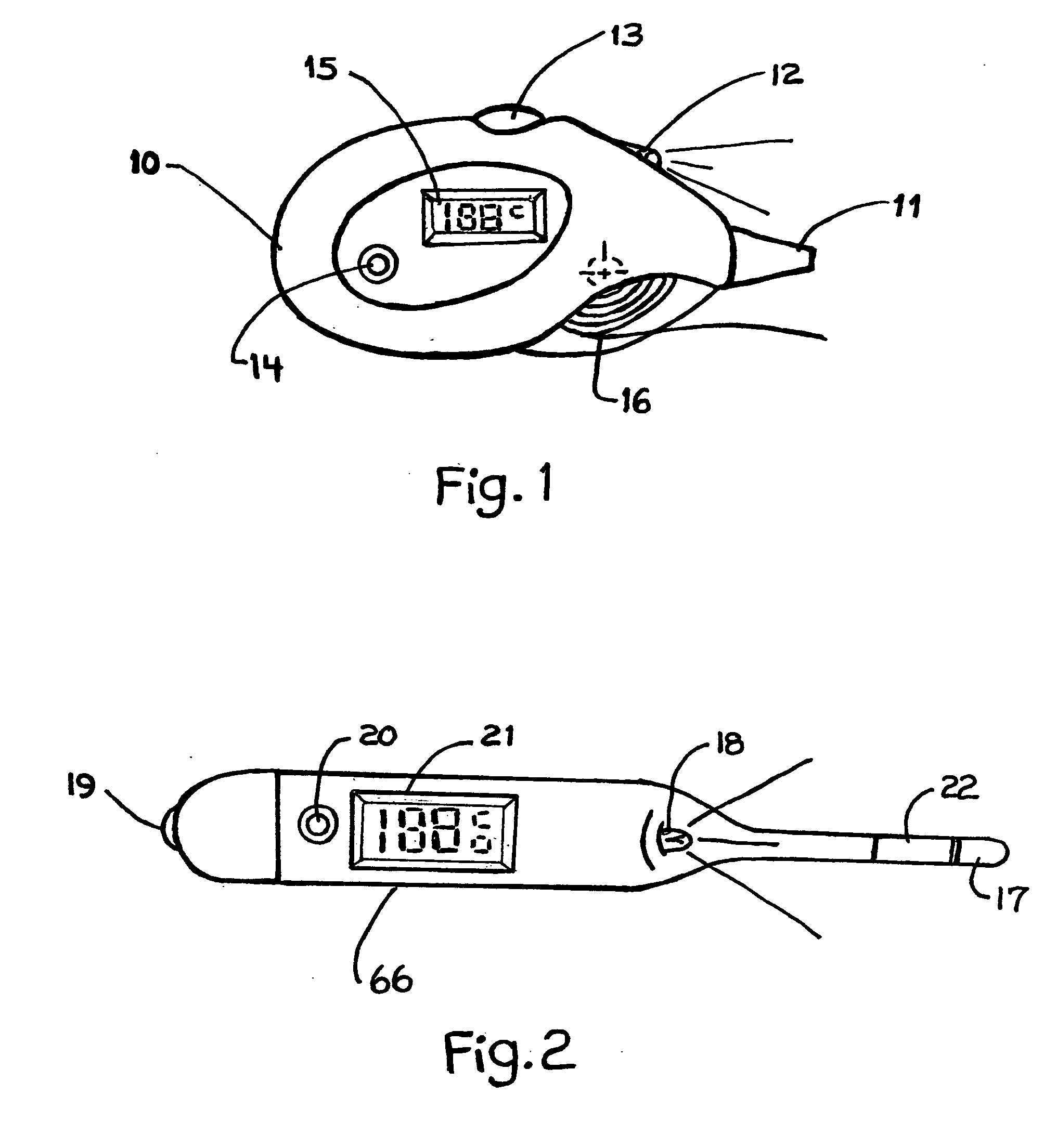
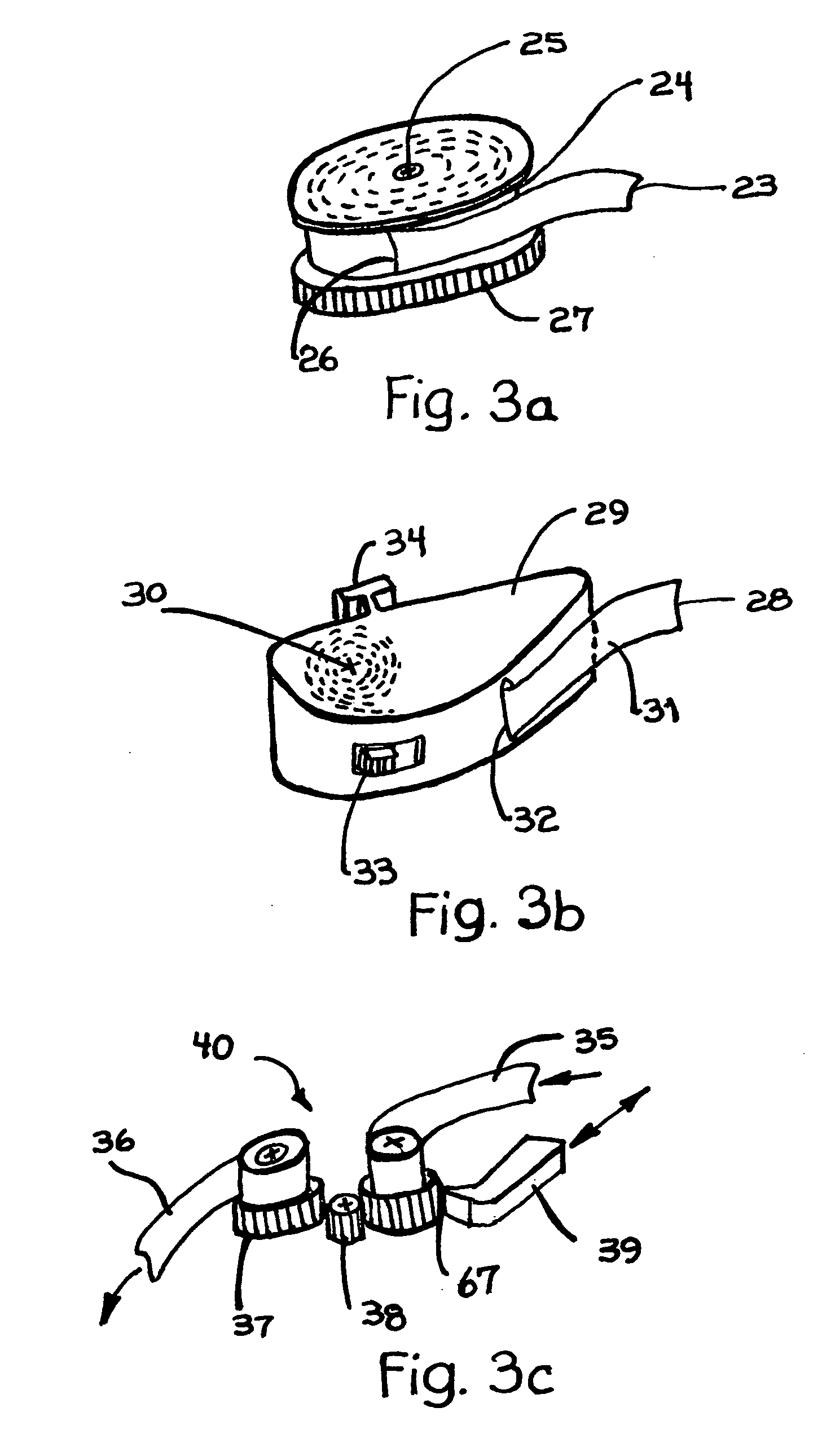
[0029] Referring to FIG. 1, a thermometer 10 includes a sensor 11, a light 12, an optional light power button 13 and a thermometer power button 14, a output display 15 to show the measurement or data from the device and an internal dispensable film cartridge 16. Depending on the style of the thermometer the components may have variations in detail but provide a means to take a temperature in an efficient time. The detail in FIG. 2. illustrates another style of a thermometer 66, that includes a sensor 17, a light 18, an optional light power button 19 and a thermometer power button 20, a display 21 to provide a visual output measurement from the device and an illuminated portion 22 of the thermometer that is made from a luminescent material or ink for ease of use in nighttime or low level lighted environments. The light is selectively operable independent of the function of the thermometer. The detail in FIG. 3a illustrates a carrier or cartridge 24, that can contain or hold the flexi...


PUM


Abstract

A temperature measure device having a light source to provide the user an effective and efficient means to take temperatures in a low-lighted area. A temperature measure device having a cartridge to store, dispense and discard the covers. The covers made of a thin narrow flexible material that is housed by a body and conveniently stored inside or in the proximity of the temperature-measuring device.

Description

CROSS REFERENCE TO RELATED ACTIONS [0001] This application claims the benefits of U.S. Provisional Application Ser. No. 60 / 472962 filed on May 23, 2003 entitled Temperature Measure device.FIELD OF THE INVENTION [0002] This invention relates to temperature measuring devices, probes and their use at night or in low-lighted areas. BACKGROUND OF THE INVENTION [0003] Thermometers are useful in the evaluation and treatment of sick or ill patients. A common practice in hospitals, physician's office or even at home, is to measure the body temperature of a patient by using a digital thermometer with a sensor or probe typically located at one end of the device. [0004] An electronic thermometer can sense the patient's temperature in a short duration of time and more so infrared thermometers can be even more effective in measuring a temperature within one second. [0005] Although thermometers have been around for many years, there has been other factors to consider in temperature measure and eas...

Claims


Application Information

Patent Timeline
IPC IPC(8): G01K7/00
CPCG01K1/06
Inventor CONFORTI, CARL J.
Owner CONFORTI CARL J
Learn More