Method and apparatus for ensuring high quality audio playback in a wireless or wired digital audio communication system

a digital audio and audio playback technology, applied in the direction of electrical equipment, transmission, synchronous/start-stop systems, etc., can solve the problems of affecting the quality of audio playback, the rate of production of digital data versus the consumption of digital data becomes a problem, and the transmission and reception of digital data are relatively uncomplicated for most wireless or wired applications. to prevent overrun of digital data

Inactive Publication Date: 2006-03-23
FREESYST
View PDF7 Cites 10 Cited by
  • Summary
  • Abstract
  • Description
  • Claims
  • Application Information

AI Technical Summary

Benefits of technology

[0025] The jitter management unit has a variable reference signal generator connected to the FIFO data retention device to provide the second reference signal for synchronization of the digital data. The buffer data retention circuit transfers the digital data to the FIFO data retention device until the FIFO data retention device contains a first amount of digital data (approximately one half of the capacity of the FIFO data retention device), where upon the FIFO data retention device begins to transmit the digital data. Further, the buffer data retention circuit must transfer all symbols of the digital data present between two marker signals to prevent overrun of the digital data. To accomplish this full transfer of all symbols between two markers, the buffer data retention device transfers the first and second symbols of a frame between two markers essentially simultaneously. This prevents any overrun of the data as transferred to the FIFO data retention circuit.

Problems solved by technology

The transmission and reception of digital data is relatively uncomplicated for most wireless or wired applications.
However, transmission of digital audio data and playing the audio back reliably at the receiver is more difficult due to the isochronous nature of the audio requirements.
For a wireless transmitter and a receiver that does not perform clock recovery from the transmitted signal, the transmitter's audio clock is different from the receiver's audio clock and thus the rate of production of the digital data versus the consumption of the digital data becomes a problem.
The transmitter's clock may be oversupplying the digital data at a faster rate than the receiver can consume the digital or alternately, the transmitter's clock may be undersupplying the digital data at a slower rate and thus starving the receiver of digital data symbols.
Further any drift in the local oscillator causes the local oscillator to have to be re-locked periodically.
Without periodic relocking of the local oscillator to the signal, there can be errors with the data reception.
Further, multipath reception problems cause the received timing data to fluctuate with the differences in the delay of the paths.
It is known that the clock recovery schemes are not perfect.
When the receiver in a wireless environment cannot receive the digital data stream due to interference in the transmission path, the phase lock loop is no longer synchronized to the transmission clock in generating the clock causing corruption or loss of the digital data.

Method used


Image

  • Method and apparatus for ensuring high quality audio playback in a wireless or wired digital audio communication system
  • Method and apparatus for ensuring high quality audio playback in a wireless or wired digital audio communication system
  • Method and apparatus for ensuring high quality audio playback in a wireless or wired digital audio communication system

Examples


Embodiment Construction

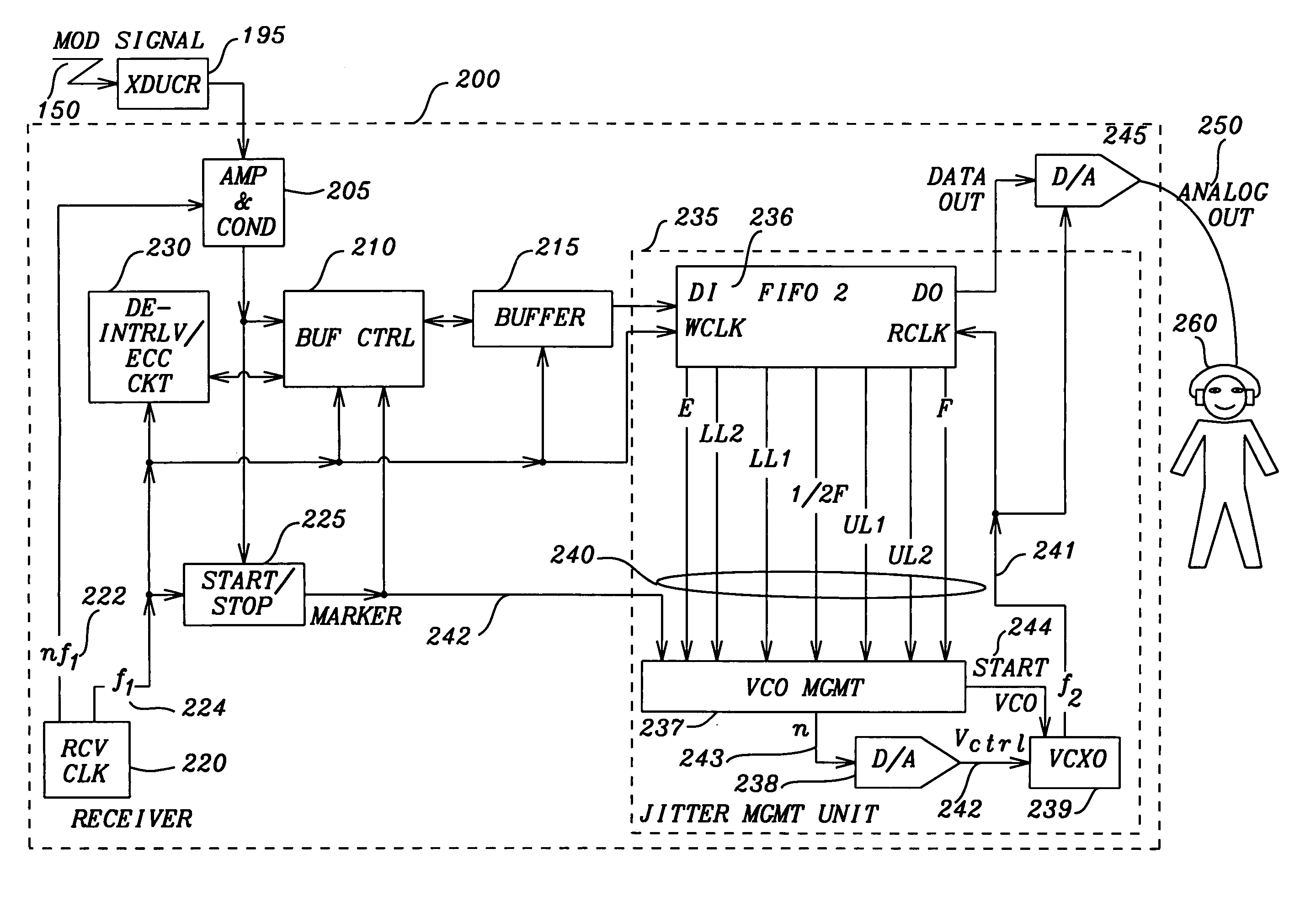
[0038] The communication system of this invention is applicable either to wired or wireless digital audio communication and provides isochronous timing of the digital data for high quality audio playback. Both the transmitter and receiver will use their own local clocks for the communication. In addition the receiver contains a jitter management unit that consists a first-in-first-out (FIFO) data retention device or buffer, a standard VCXO (Voltage controlled crystal oscillator) and a VCXO control logic unit. This jitter management unit tracks the transmitter's audio clock by making use of the FIFO buffer status only and is simple to implement or integrate into any digital audio systems that separates the playback from the source.

[0039] The FIFO buffer is analogous to a container and the producer (receiver) pours in digital data symbols of the analog audio signal at a rate that is equivalent to the receiver's clock period. This container is empty at the beginning and the consumer (...


PUM


Abstract

A communication system synchronizes data received and recovered from a transmission medium to the data transmitted such the there is neither under-run nor overrun of the data due to differences in the transmission and reception timing. The data communication system has a transmitter and a receiver. The transmitter encodes digital data into series of symbols and transmits a modulated signal composed of the series of symbols. The receiver acquires the modulated signal, restoring the modulated signal, reconstructing the symbols of the digital data from the modulated signal and synchronizing the digital data to a first reference signal. The digital data is transferred to a buffer data retention circuit. The digital data is transferred from the buffer retention circuit to a jitter management unit. A boundary marker signal detection circuit extracts a marker signal indicating a boundary of symbols of the digital data to provide an indication of the timing of the digital data as broadcasted by the transmitter. A jitter management unit synchronizes the digital data to the first reference signal. The jitter management unit has a FIFO buffer to receive the reconstructed digital data at the rate of the first reference signal from the buffer retention circuit and transmits the synchronized digital data at a rate approximating the timing of the transmitter. The jitter management unit synchronizes the digital data by monitoring the level of the digital data present within the FIFO buffer and adjusting the consumption of the digital data from the FIFO buffer.

Description

BACKGROUND OF THE INVENTION [0001] This application claims priority to U.S. Provisional Patent Application Ser. No. 60 / 612,007, filed on Sep. 22, 2004, which is herein incorporated by reference.RELATED PATENT APPLICATIONS [0002]“An Apparatus and Method for Adaptive Digital Locking and Soft Evaluation of Data Symbols in a Wireless Digital Communication System,” Provisional U.S. Patent Application Ser. No. 60 / 612,008, Filing Date Sep. 22, 2004, assigned to the same assignee as this invention. FIELD OF THE INVENTION [0003] This invention relates to apparatus and methods for transmission and reception of digital data communication signals. More particularly, this invention relates to the synchronization of received digital data communication signals. DESCRIPTION OF RELATED ART [0004] The transmission and reception of digital data is relatively uncomplicated for most wireless or wired applications. However, transmission of digital audio data and playing the audio back reliably at the rec...

Claims


Application Information

Patent Timeline
Patent Type & Authority Applications(United States)
IPC IPC(8): H04L7/00
CPCH04J3/0632H04L7/005H04L7/033
Inventor CHUA, BENG HUAT
Owner FREESYST
Why Eureka
Try Eureka