

Catalyst and a method for manufacturing the same
a catalyst and catalyst technology, applied in the field of catalysts, can solve the problems of poor structural and physical strength of platinum black, inefficient transfer of electrical charge, and high cost of materials
- Summary
- Abstract
- Description
- Claims
- Application Information
AI Technical Summary
Benefits of technology
Problems solved by technology
Method used
Image

Examples
example 1
Electroplating Palladium on a Conductive Substrate Palladium Plating Solution Preparation
[0087] 2.7 g sodium dihydrogen phosphate (NaH2PO4) and 3.2 g disodium hydrogen phosphate (Na2HPO4) [Fluka] were dissolved in 100 ml deionized water, and stirred by magnetic stirring for 30 minutes. The concentrations for NaH2PO4 and Na2HPO4 were equally 225 mM. Then 0.18 g Palladium chloride (PdCl2) [Aldrich] was added to the phosphate solution. The solution was then stirred for 30 minutes and filtered to black solids. The PdCl2 concentration was about 5 mM. The pH of the solution was measured at 6.8. The color of the solution was brown. The solution was deaerated before the plating process by bubbling nitrogen through the solution.
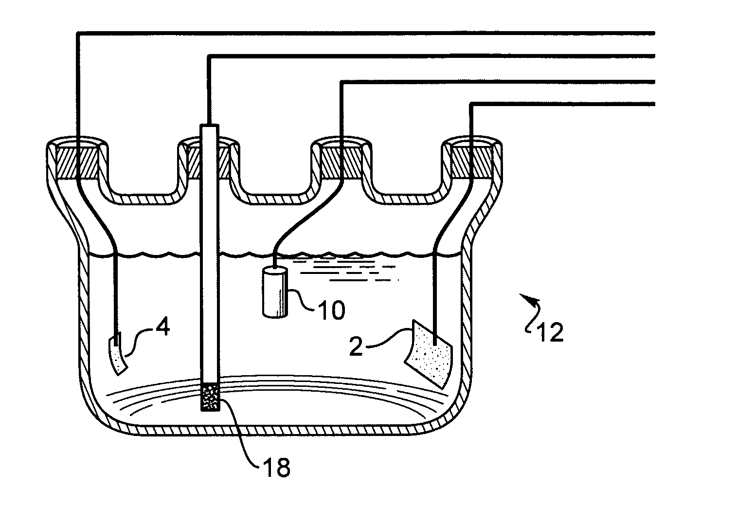
Preparation of the Substrate
[0088] A thin-film platinum polyimide array was used for palladium plating. The array included 16 electrodes with 200 μm thin-film Pt disk as exposed electrode surface. All the electrodes in the array were shorted to common contact point...
example 2
Electroplating Iridium on a Conductive Substrate Iridium Plating Solution Preparation
[0094] 0.3 g sodium dihydrogen phosphate (NaH2PO4) and 6.03 g disodium hydrogen phosphate (Na2HPO4) [Fluka] were dissolved in 100 ml deionized water, magnetic stirring for 30 minutes. The concentrations for NaH2PO4 and Na2HPO4 were 25 mM and 425 mM, respectively. Then 0.882 g of Ammonium hexachloroiridate ((NH4)2IrCl6) from [Alfa Aesar] was added to the phosphate solution to form the iridium salt concentrations of 20 mM. The solution was stirred for 30 minutes prior to plating. The pH of the solution was measured at 7.9. The initial color of the solution is brown and changed to dark blue after overnight aging.
Preparation of the Substrate
[0095] A thin-film platinum polyimide array was used for iridium plating. The array had 16 electrodes with 200 μm thin-film Pt disk as exposed electrode surface. All electrodes in the array were shorted to a common contact points for the plating. The Pt disk elect...
example 3
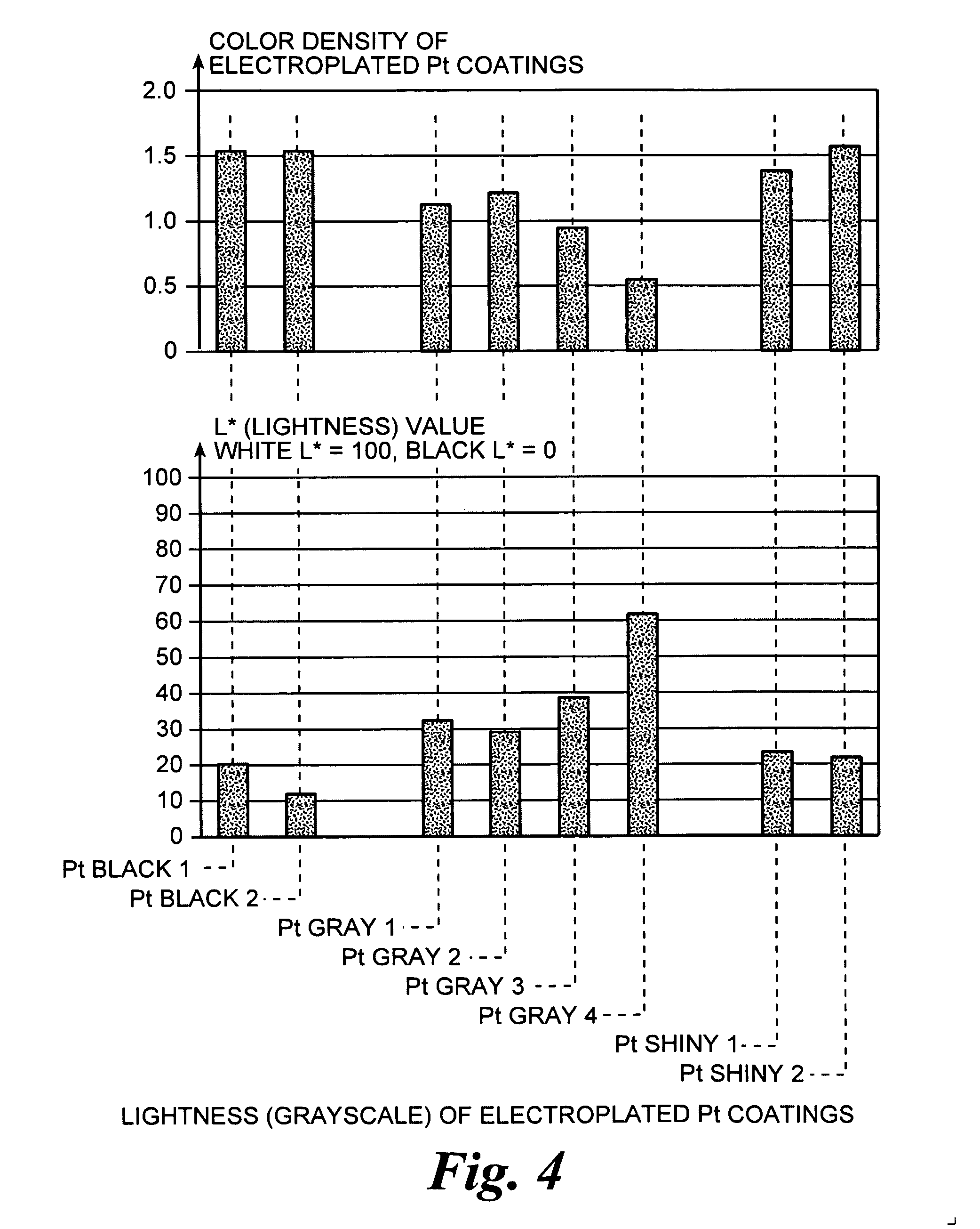
Electroplating Platinum on a Conductive Substrate Platinum Plating Solution Preparation
[0101] 0.3 g sodium dihydrogen phosphate (NaH2PO4) and 6.03 g disodium hydrogen phosphate (Na2HPO4) [Fluka] were dissolved in 100 ml deionized water, and stirred by magnetic stirring for 30 minutes. The concentrations for NaH2PO4 and Na2HPO4 were 25 mM and 425 mM. Then 0.5 g of Platinum chloride (PtCl4) [Alfa Aesar] was added to the phosphate solution to form the platinum salt concentrations of 15 mM. The solution was then stirred for 30 minutes. Different concentrations of (PtCl4) were used in the experiments and the range of Pt salt concentrations was from 3 to 30 mM. The pH of the solution was measured at 7.9. The color of the solution was amber. The solution was deaerated before the plating process by bubbling nitrogen through the solution.
Preparation of the Substrate
[0102] A thin-film platinum polyimide array was used for platinum plating. The array included 16 electrodes with 200 μm thin-...
PUM
| Property | Measurement | Unit |
|---|---|---|
| thickness | aaaaa | aaaaa |
| voltage | aaaaa | aaaaa |
| voltage | aaaaa | aaaaa |
Abstract
Description
Claims
Application Information