Bladder

Active Publication Date: 2006-03-23
ADIDAS
View PDF86 Cites 85 Cited by
  • Summary
  • Abstract
  • Description
  • Claims
  • Application Information

AI Technical Summary

Benefits of technology

[0018] In various embodiments, the pulling elements can be substantially inelastic and may include multiple pairs of pulling elements defining substantially identical angles. Each of the pulling elements may be subjected to a tensile force between the electronic device and the bladder and arranged such that a summation of the tensile forces on the electronic device equals substantially 0. Such an arrangement maintains the electronic device in static equilibrium in any orientation of the bladder, for example, while the bladder is rotating. The plurality of pulling elements provides a restoring force to the electronic device subsequent to a foot strike to maintain the device in the predetermined position. The restoring force aids post impact recovery of the electronic device by, for example, returning the electronic device quickly to its predetermined position.
[0019] In additional embodiments, the device can be arranged inside a separate chamber within the bladder. The chamber provides additional protection for the sensitive components of the electronic device. This applies not only to the use, but also to the assembly, when the device is at first inserted into the bladder and not yet protected by its cushioning suspension against impacts or other mechanical loads. The chamber can be defined by a plurality of auxiliary surfaces extending between the pulling elements, thereby creating an additional separate air cushion around the electronic device for providing improved cushioning.
[0020] In one embodiment, the chamber includes a rounded, substantially spherical shape; however, other shapes are contemplated and within the scope of the invention. A rounded, spherical shape provides maximum protection against arising mechanical loads. If under an extreme deformation of the bladder, for example during a penalty shot of a soccer ball, the outer surface is deformed to more than the predetermined position of the device, the rounded shape of the chamber assures that the arising impact deflects the chamber to the side and does not cause a maximum acceleration of the component, which could destroy the sensitive electronics. Moreover, a spherical shape ensures a weight distribution within the bladder having maximum symmetry, so that the mechanical properties and the flight

Problems solved by technology

Furthermore, they dampen, similar to an oil pressure bumper, an arising oscillation of the device,

Method used


Image

  • Bladder
  • Bladder
  • Bladder

Examples


Embodiment Construction

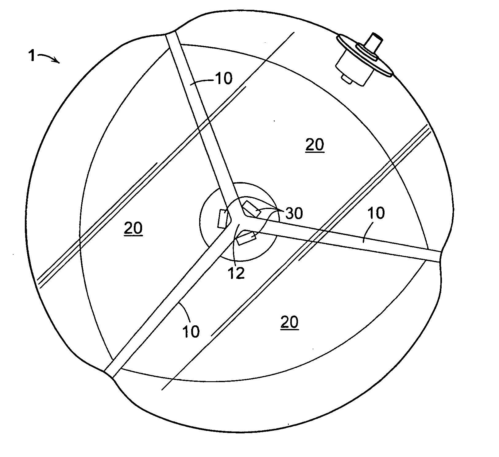
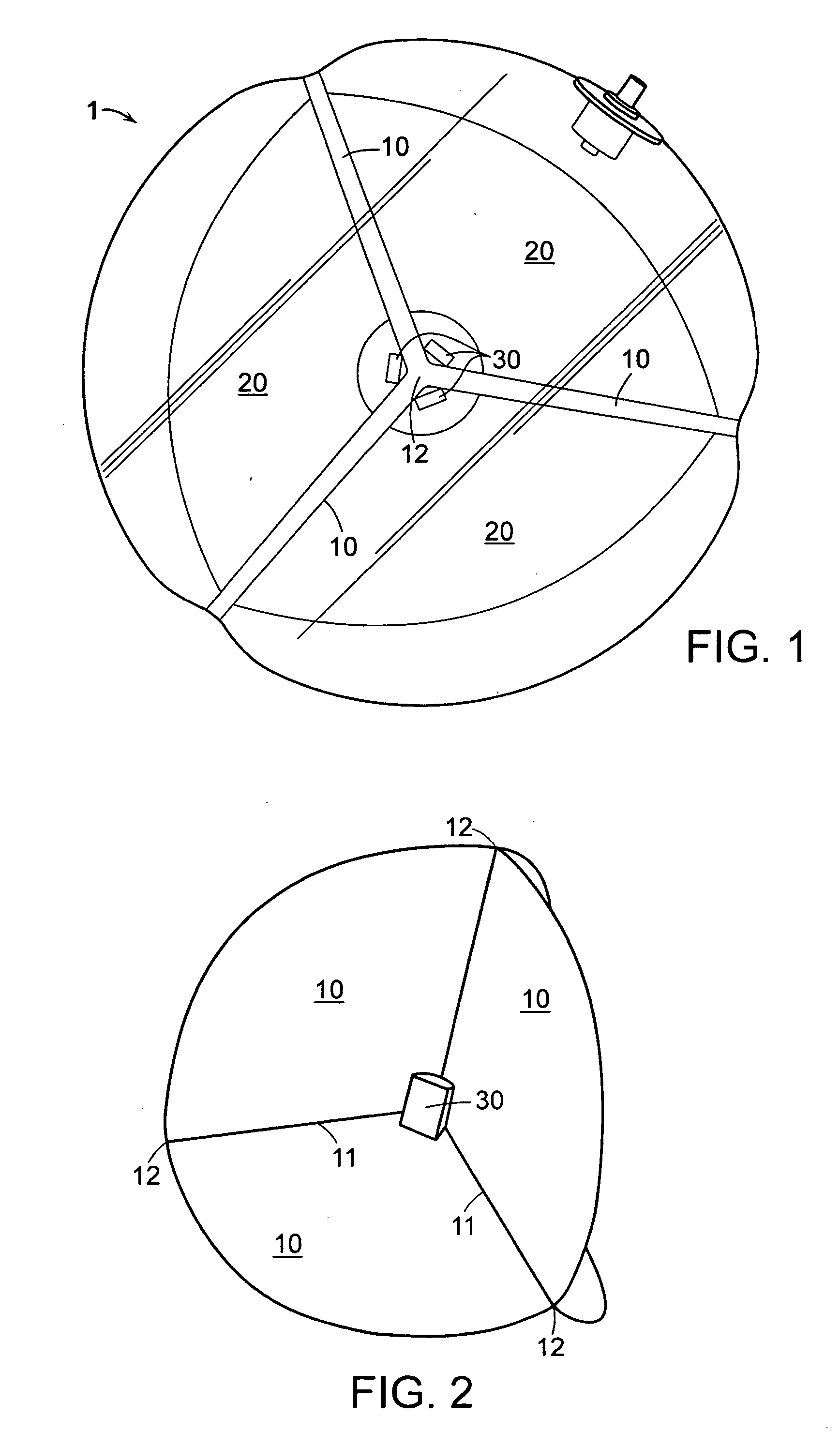
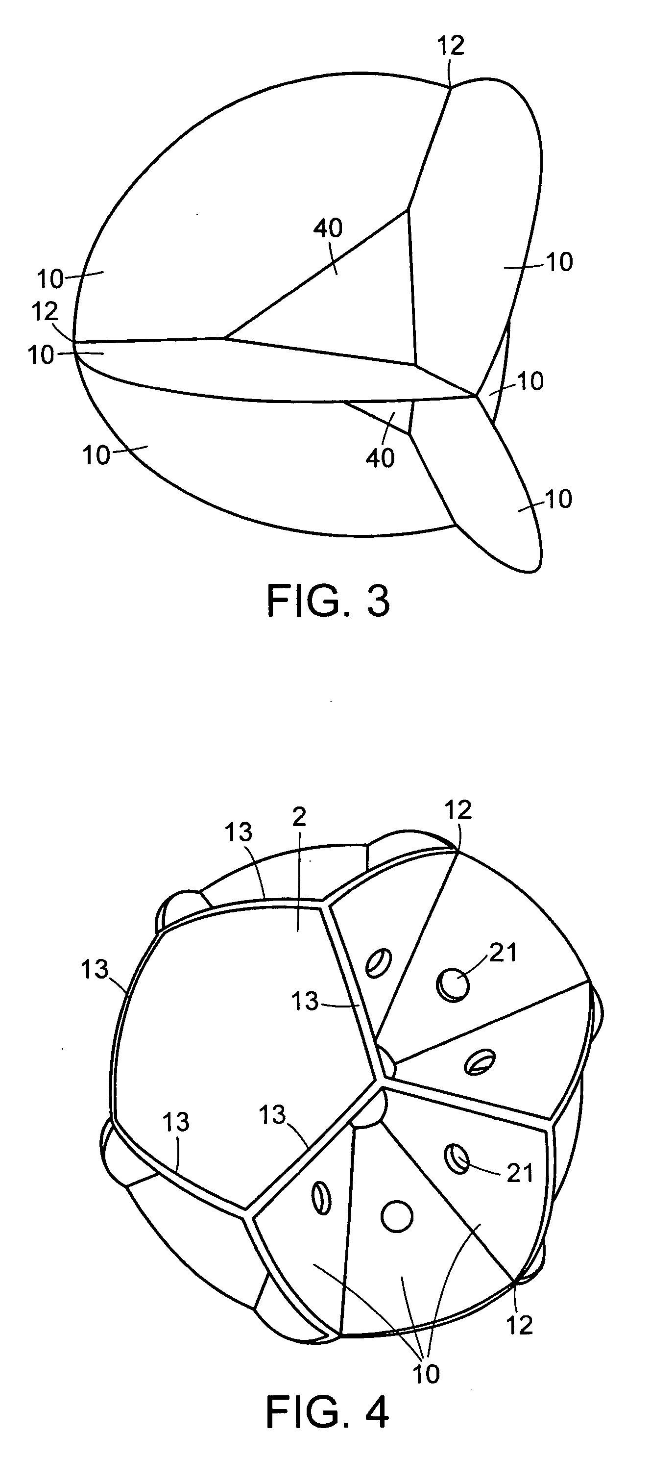
[0051] In the following, various embodiments of the present invention are described with reference to a bladder for a soccer ball, wherein a transmitter is positioned inside the bladder for use in a tracking system. It is, however, to be understood that the present invention can also be used for other balls using an inflatable bladder, such as handballs, volleyballs, rugby balls, or basketballs. Further, a different device can be arranged in the interior of the bladder instead of the transmitter, for example, a simple pressure sensor or a device for providing acoustic signals, or any other device which uses electric current for measurement purposes or for providing a signal. Also, a passive reflector for electromagnetic waves and a global positioning system are considered to be electronic devices in the meaning of the present invention.

[0052] If the transmitter or other device is an active electronic component requiring a power supply, an accumulator, for example, may be used to su...


PUM


Abstract

The invention relates to a bladder for an inflatable ball including structure for receiving an electronic device therein. The structure facilitates at least one of cushioning, positioning, locating, and supporting the electronic device. The structure cushions reaction forces arising from a foot strike to the bladder and/or provides a restoring force to the electronic device subsequent to a foot strike to maintain the device in its predetermined position.

Description

CROSS-REFERENCE TO RELATED APPLICATION [0001] This application claims priority to and the benefit of, German patent application serial number 102004045176.1, filed on Sep. 17, 2004, the entire disclosure of which is hereby incorporated by reference herein. TECHNICAL FIELD [0002] The present invention relates to a bladder for an inflatable ball, in particular a soccer ball. BACKGROUND OF THE INVENTION [0003] In many sports, such as soccer, handball, or volleyball, it is desirable to provide additional information regarding various parameters of the sport to individuals watching the game. This concerns, for example, the position of the players and the ball at any time during the game, information concerning the velocity of the ball, and the speed and performance of individual players. Also, referees and other persons monitoring the game for compliance with the rules may benefit from such information and control the game more reliably. Additionally, it is also reasonable from a trainer...

Claims


Application Information

Patent Timeline
IPC IPC(8): A63B41/08
CPCA63B41/02A63B43/00A63B2225/50A63B71/0605A63B2041/005A63B43/007
Inventor NURNBERG, HANS PETERDRURY, DAVID JOHNLUCAS, TIMOTHY DAVIDSEYDEL, ROLAND GUNTER
Owner ADIDAS
Why Eureka
Try Eureka