Method for monitoring thermal heating during magnetic resonance imaging

a magnetic resonance imaging and thermal imaging technology, applied in the field of nuclear magnetic resonance imaging (mri) methods and systems, can solve the problems that the thermal imaging method for producing thermal maps has not been demonstrated to work at high field strengths, and achieve the effects of accurate control of the image acquisition process, shortening the scan time of mri procedures, and accurate detection of sar tissue heating

Inactive Publication Date: 2006-03-23
GENERAL ELECTRIC CO +1
View PDF22 Cites 32 Cited by
  • Summary
  • Abstract
  • Description
  • Claims
  • Application Information

AI Technical Summary

Benefits of technology

[0012] A general object of the present invention is to provide a more accurate detection of SAR tissue heating and provide a more accurate control of the image acquisition process. The acquired thermal images may be examined on a pixel-by-pixel basis to actually measure tissue heating at specific locations in the subject. Hot spots may thus be found and used to control the image acquisition process rather than some average presumed temperature increase based on applied RF power.
[0013] Another object of the invention is to shorten the scan time of MRI procedures. Because prior SAR monitoring systems are based on RF power applied throughout the subject, very large safety factors are included to insure that tissue temperature does not increase to an undesirable level at any location in the subject. The present method actually measures tissue temperature increases throughout the subject and the rate of image data acquisition is slowed only when tissue temperature actually rises to an undesirable level at any location in the subject.

Problems solved by technology

The PRF method for producing thermal maps has not been demonstrated to work at high field strengths.

Method used


Image

  • Method for monitoring thermal heating during magnetic resonance imaging
  • Method for monitoring thermal heating during magnetic resonance imaging
  • Method for monitoring thermal heating during magnetic resonance imaging

Examples


Embodiment Construction

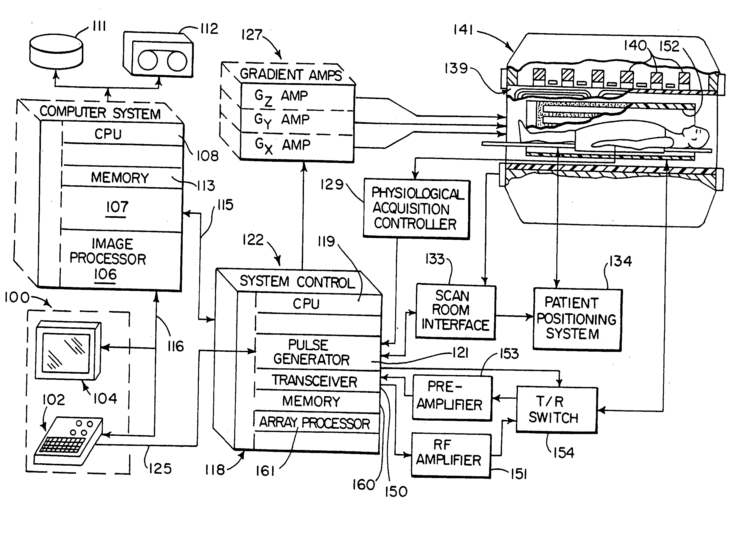
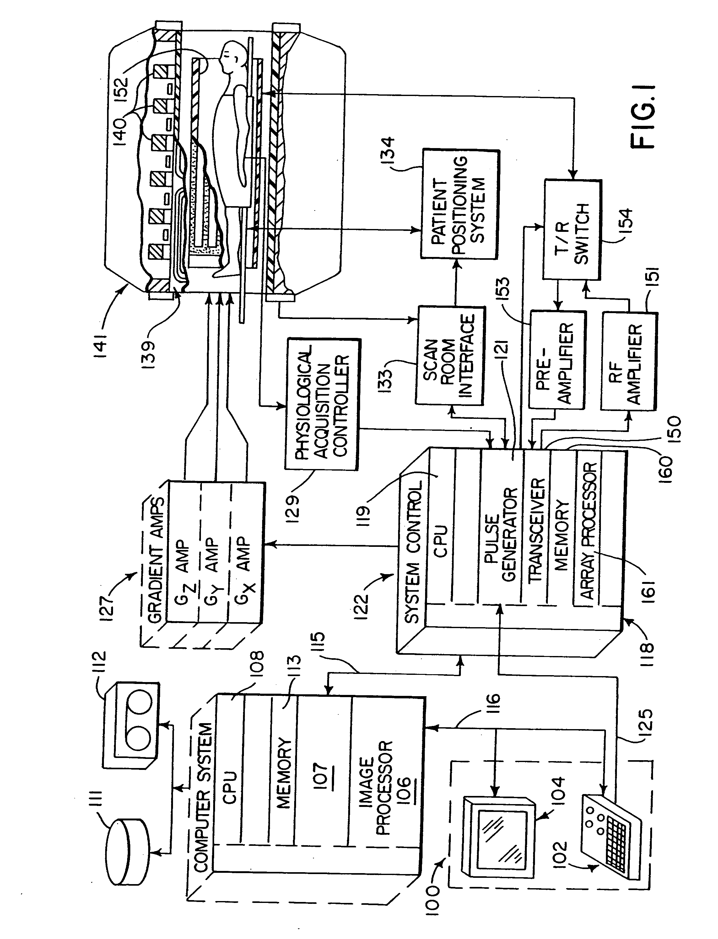
[0026] Referring first to FIG. 1, there is shown the major components of a preferred MRI system which incorporates the present invention. The operation of the system is controlled from an operator console 100 which includes a keyboard and control panel 102 and a display 104. The console 100 communicates through a link 116 with a separate computer system 107 that enables an operator to control the production and display of images on the screen 104. The computer system 107 includes a number of modules which communicate with each other through a backplane. These include an image processor module 106, a CPU module 108 and a memory module 113, known in the art as a frame buffer for storing image data arrays. The computer system 107 is linked to a disk storage 111 and a tape drive 112 for storage of image data and programs, and it communicates with a separate system control 112 through a high speed serial link 115.

[0027] The system control 122 includes a set of modules connected together...


PUM


Abstract

The SAR exposure of a subject undergoing an MRI examination is measured by acquiring a thermal image that indicates that temperature increase caused by the SAR exposure. This measurement may be used in a prescan process to adjust the SAR load produced by a prescribed imaging pulse sequence, and it can be used during the scan to adjust the SAR load produced by the prescribed imaging pulse sequence.

Description

STATEMENT REGARDING FEDERALLY SPONSORED RESEARCH [0001] This invention was made with government support under Grant Nos. HL067029 and CA86278 awarded by the National Institute of Health. The United States Government has certain rights in this invention.BACKGROUND OF THE INVENTION [0002] The field of the invention is nuclear magnetic resonance imaging (MRI) methods and systems. More particularly, the invention relates to the measurement and limitation of RF power produced by an MRI system during a patient scan. [0003] When a substance such as human tissue is subjected to a uniform magnetic field (polarizing field B0), the individual magnetic moments of the spins in the tissue attempt to align with this polarizing field, but precess about it in random order at their characteristic Larmor frequency. If the substance, or tissue, is subjected to a radio frequency (RF) magnetic field (excitation field B1) which is in the x-y plane and which is near the Larmor frequency, the net aligned mo...

Claims


Application Information

Patent Timeline
Patent Type & Authority Applications(United States)
IPC IPC(8): A61B5/05
CPCA61B5/055A61B5/015A61B5/0037
Inventor GRIST, THOMAS M.ZHOU, YONG
Owner GENERAL ELECTRIC CO
Why Eureka
Try Eureka