System and method for externally controlled surgical navigation

a surgical navigation and external control technology, applied in the field of medical procedures, can solve the problems of transmitter not being repositioned, difficult to properly guide surgical tools and/or implants when they are inside the body, and overall inaccuracy of the system

a surgical navigation and external control technology, applied in the field of medical procedures, can solve the problems of transmitter not being repositioned, difficult to properly guide surgical tools and/or implants when they are inside the body, and overall inaccuracy of the system

US20060064005A1Inactive Publication Date: 2006-03-23INNOVATIVE SPINAL TECH

Image

  • System and method for externally controlled surgical navigation
  • System and method for externally controlled surgical navigation
  • System and method for externally controlled surgical navigation

Examples


Embodiment Construction

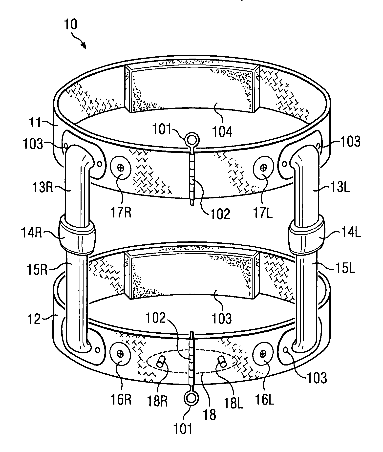
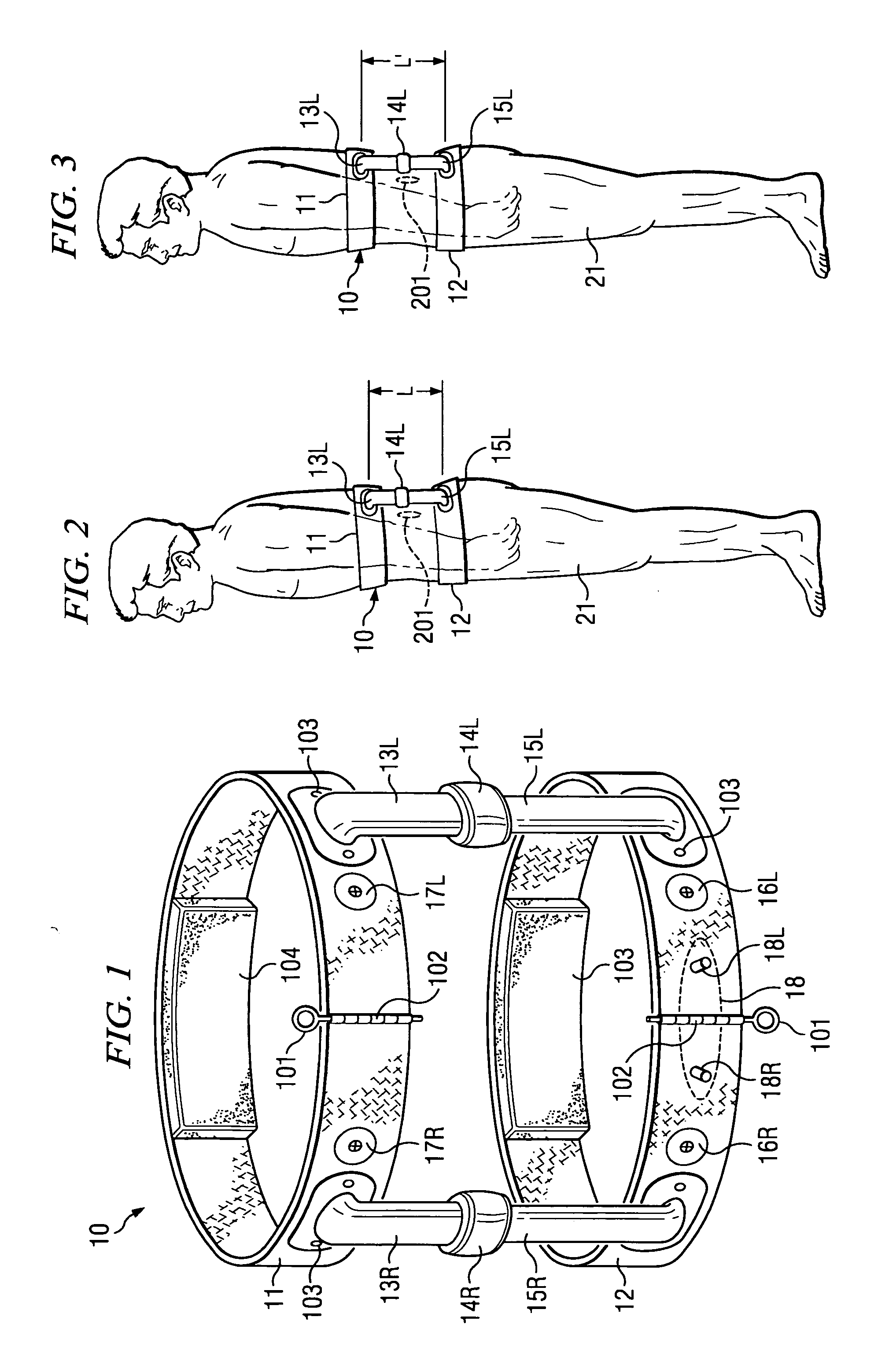
[0015] Turning now to FIG. 1, there is shown one embodiment of externally controlled surgical device 10. Device 10 can be used for surgical navigation, as well as for rigid positioning for a variety of surgical procedures, such as biopsy of soft tissue. The lower portion of device 12 is strapped around a portion of the patient below a target area, and band 11 is strapped around a portion of the patient on the other side of the target area. For example, when used in a spinal operation, the lower portion 12 may be strapped around the hips of the patient, and the upper band 11 may be strapped around the torso of the patient on a side of the target area opposite that of lower band 12. That is, in a spinal operation upper band 11 may be arranged, for example, above the vertebrae or disc to be operated on and lower band 12 may be arranged below the portion to be operated on which is the target site. Pads 103 and 104 can be placed all the way around the respective bands 11 and 12 or in cer...


PUM


Abstract

The present invention is directed to a system and method which allows for the mounting of a medical navigation system external to a patient. In one embodiment, displacement device is mounted around a patient's torso and serves to displace (e.g., distract or compress) the patient's skeleton in a manner such that the target site becomes fixed relative to a site on the displacement device. A navigation transmitter can then be mounted to the displacement device. The device has a quick disconnect that allows it to be removed without first releasing the displacement. Displacement can be controlled by pneumatic, hydraulic, electrical or by screw action. In one embodiment, the device can be used to position a patient on an operating table.

Description

TECHNICAL FIELD [0001] This invention relates to medical procedures and more particularly to such procedures where it is necessary to track the location of tools and / or devices within a body being operated upon. BACKGROUND OF THE INVENTION [0002] Many medical procedures, such as spinal operations, are now routinely performed in a minimally invasive manner, the desire being to reduce the trauma to the skin, soft tissue, and muscle as much as possible. A problem exists in such minimally invasive medical techniques in that when small skin incisions are made sight lines become non-existent and thus it is difficult to properly guide the surgical tools and / or implants when they are inside the body. [0003] One method for such guidance is to continually take fluoroscope (X-ray) pictures as the procedure progresses. This is slow and suffers from problems due to harmful exposure for patients and medical personnel. [0004] Another method uses fluoroscopy (X-ray) and electro magnetic electronic ...

Claims


Application Information

Patent Timeline
23 Mar 2006
Publication
US20060064005A1
IPC
A61B5/05
CPC
A61B6/04; A61B6/0421; A61B19/201; A61B19/203; A61B2019/5483; A61B19/5244; A61B19/54; A61B2019/302
Inventors
TRIANO, JOHN J.; ROGERS, CAROLYN