

Radiotherapy treatment monitoring using ultrasound
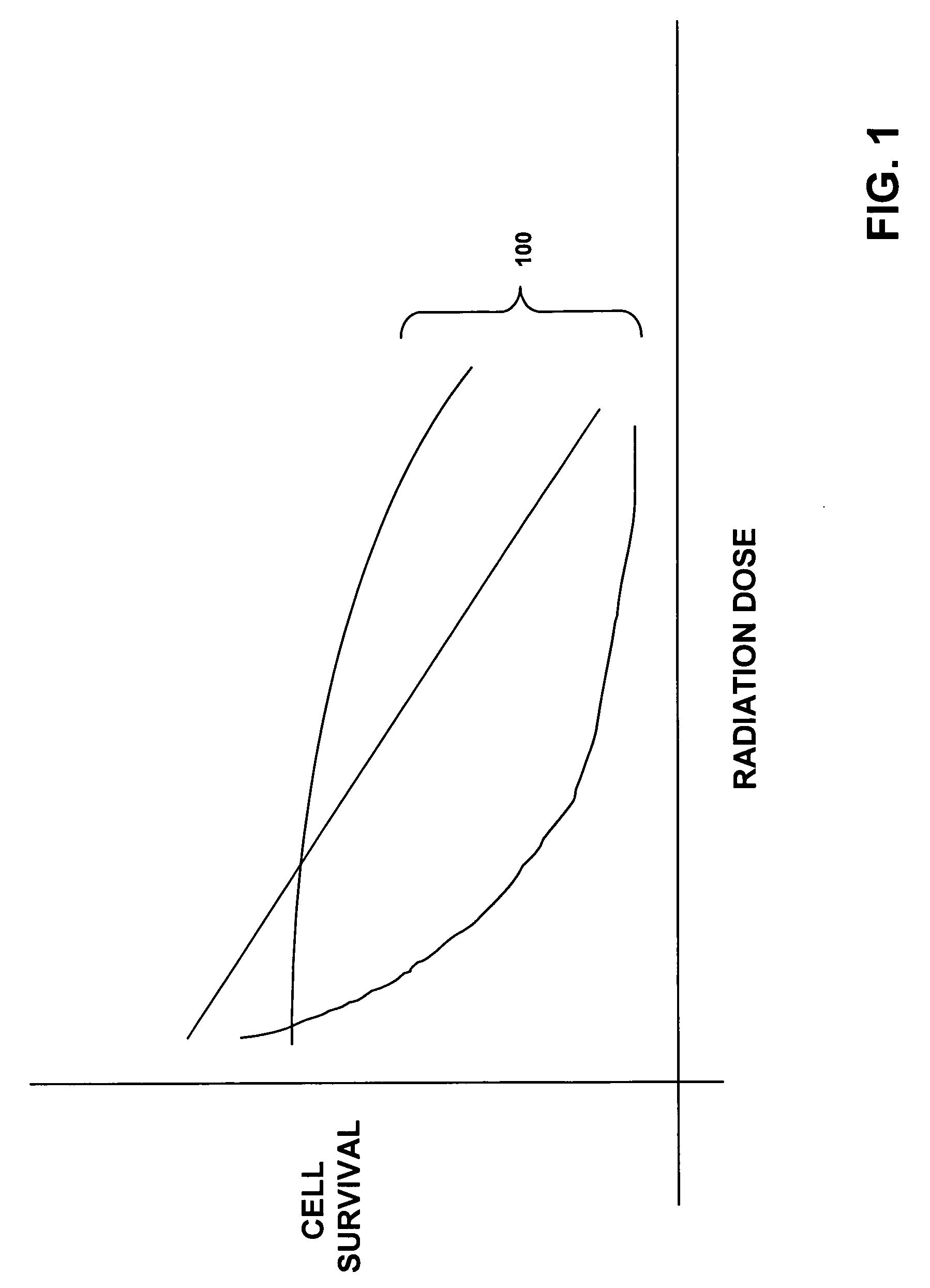
a technology of radiation treatment and ultrasound, applied in the direction of radiation therapy, catheters, reradiation, etc., can solve the problems of cell death, inability to accurately predict the actual dose response curve of a particular patient and/or organ, and difficult to relate the prescribed physical dose to the biological effect of radiation on the actual tissue being treated
- Summary
- Abstract
- Description
- Claims
- Application Information
AI Technical Summary
Benefits of technology
Problems solved by technology
Method used
Image

Examples
Embodiment Construction
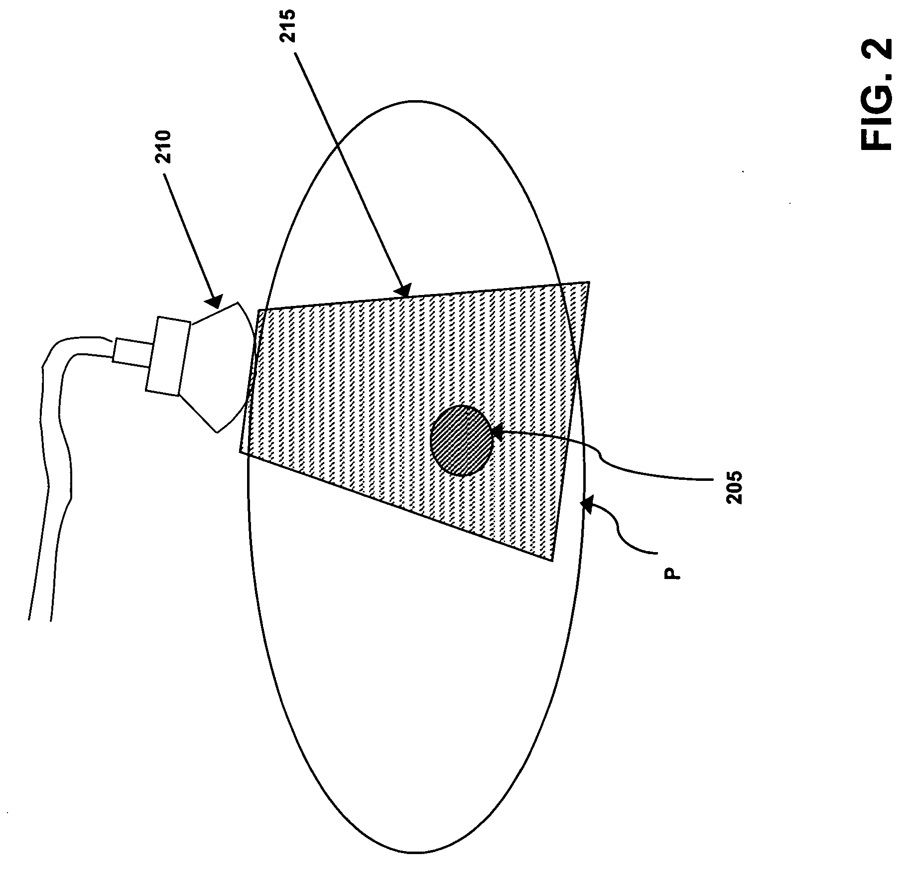
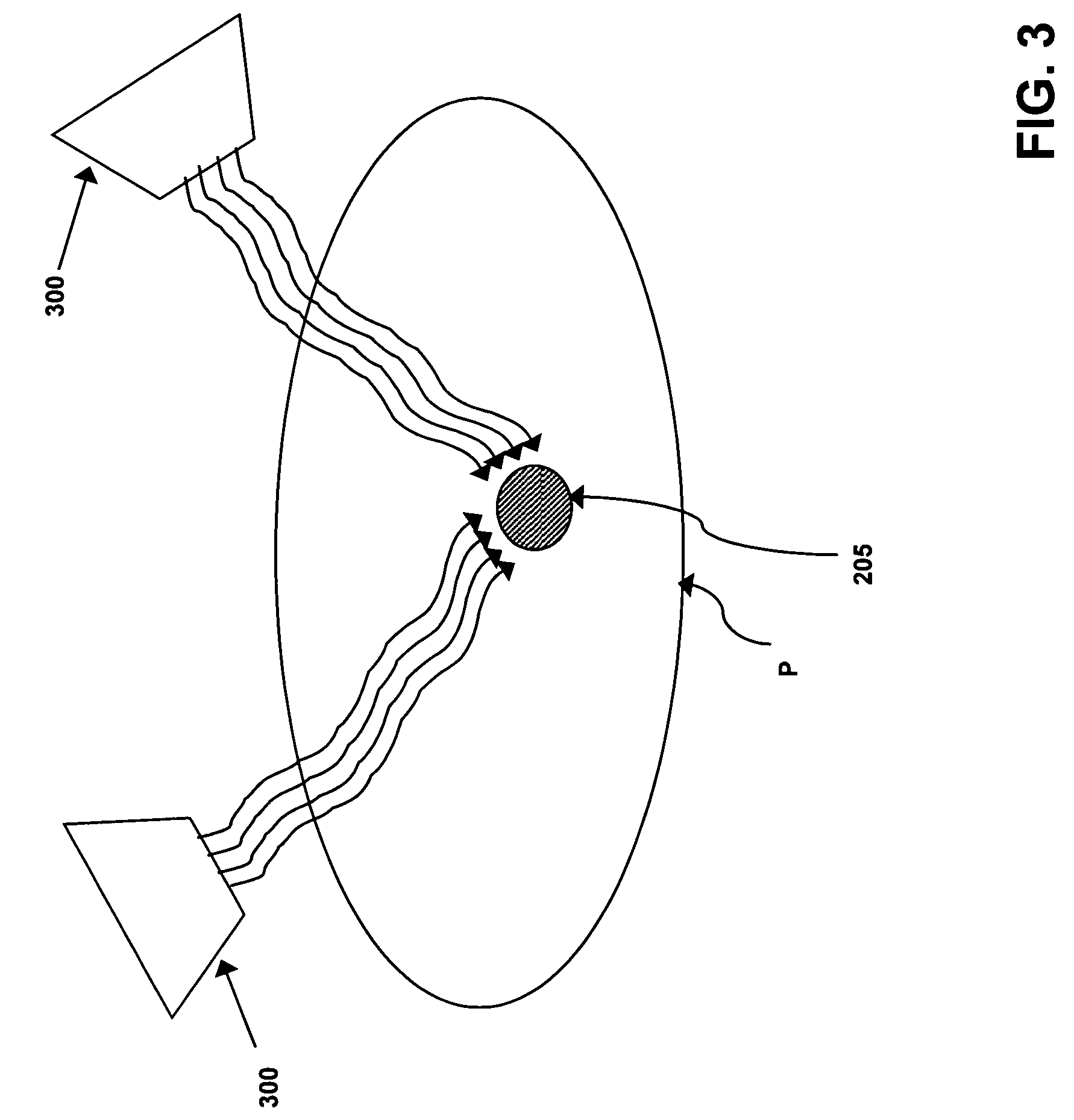
[0024] Throughout the following descriptions and examples, the invention is described in the context of monitoring and measuring the effects of radiotherapy as administered to a cancerous tumor or lesion. However, it is to be understood that the present invention may be applied to monitoring various physical and / or biological attributes of virtually any mass within or on a patient in response to any form of treatment. For example, the therapy can include one or more of radiation, cryotherapy, or any other treatment method that can affect tissue biology at the cellular level.
[0025] Typically, B-mode medical ultrasound consists of pressure waves (referred to as RF image data) that are detected by transducers and converted to pixel values by extracting the envelope of the waves. One imaging parameter in ultrasound is the operational frequency. Generally, the higher the frequency, the better the intrinsic resolution of the images produced by the ultrasound system. Because the attenuati...
PUM
 Abstract
Description
Claims
Application Information