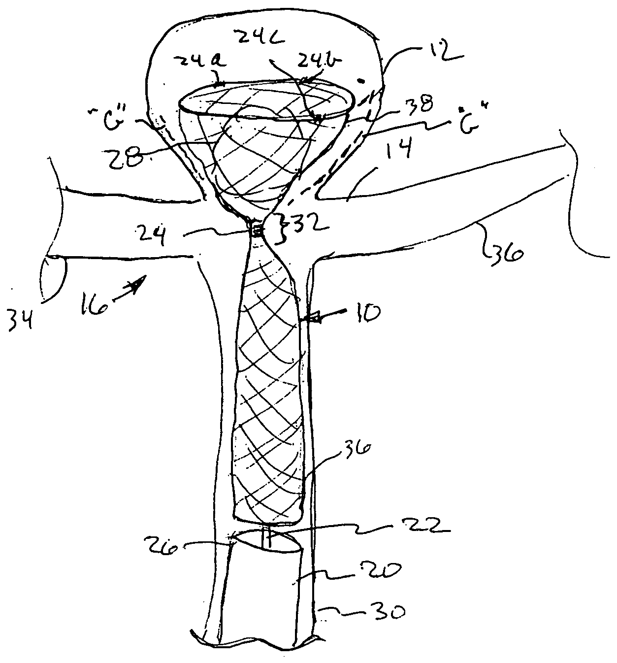
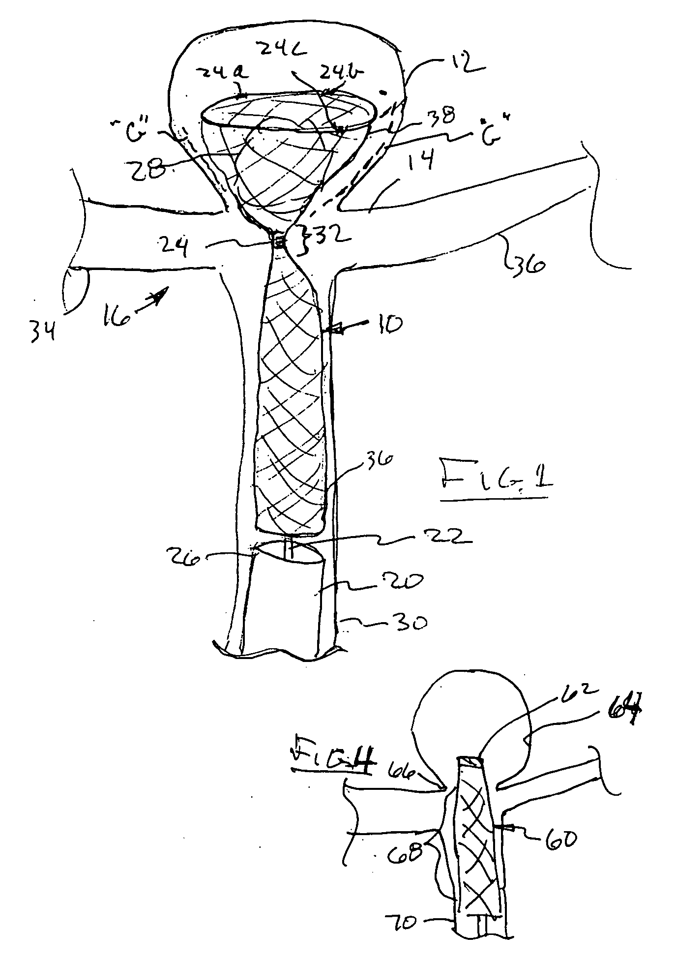
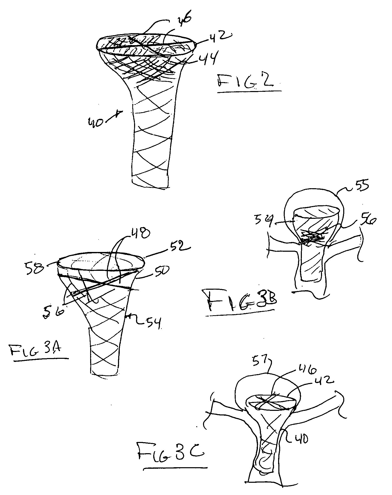
[0017] A yet further embodiment of the present invention comprises an elongated mesh sleeve having a proximal open end and a tapered distal closed or
leading edge end. The mesh sleeve may be made in one preferred embodiment, of a shape memory material, such as a shape memory
metal alloy, or a shape memory
thermoplastic. The internal control shaft or push rod is preferably utilized to deliver the tapered-end sleeve through a micro-
catheter into the central portion of an aneurysm disposed at a bifurcation. The
distal portion of the tapered sleeve through its shape memory means, or through its attachment to the control shaft, may be folded proximally so that the tapered otherwise distal-edge, is now pulled or folded back within the main body portion of the sleeve. Thus, a cup-shaped mesh, now comprising a double thickness, sits within the lower girth of the aneurysm at the bifurcated orifice. The control shaft may be removed from the tapered tip of the
leading edge of the sleeve by a release joint or by electrolytic action or a dissolvable connection there-between. Flow of blood is preferably through the center of the device and out to the side branches to minimize flow into the aneurysm, but in further embodiments, the diameter of the main body portion of the mesh sleeve may be such as to permit
blood flow around the circumference thereof, as well as the major
blood flow through the openings within the mesh. Utilizing an inverted form of the tapered sleeve permits a mesh material of relatively wider openings therethrough, because by virtue of the doubling back and folding over of the mesh material during its inversion effectively one thus creates a mesh of comparable
porosity (two
layers) to that of an otherwise tighter mesh, so as to comparatively inhibit embolitic material from escaping the aneurysm once that device has been put in place.
[0018] A further embodiment of the present invention comprises a mesh
implant having a rather bulbous distal- or leading end, and a generally cylindrical body portion comprising its proximal end. The proximal end is open to permit the use of a pushrod or
control rod, allowing the expandable bulbous end to be narrowed during its deployment within aneurysm between a pair of side branches. Upon release of the
control rod from the distal end of the device, the bulbous portion assumes its enlarged configuration with a slightly tapering proximal portion of the bulbous end nesting within the orifice defining the aneurysm. The tapered, narrowed-diameter portion of the body of the present device is foraminous end of sufficient narrow diameter, so as to permit blood flow therearound and therethrough, while the bulbous portion prevents embolitic material from escaping into the side branches.
[0019] The bulbous device of the aforementioned embodiment may include an arrangement of struts or shape memory members of
metal or
thermoplastic, formed across the proximal portion of the bulbous end of the stent device. The device is positioned at a bifurcation with its bulbous end within the aneurysm. A staging, or
cross cut strut arrangement, is positioned preferably at the orifice of the aneurysm. A micro-
catheter may be positioned through or adjacent the proximal body portion of the device to deliver embolic material into the aneurysm. The stage, or cross struts, help to contain the embolitic material within the aneurysm, and prevent it from passing the
transition point between the bulbous portion and the tubular body portion of the device. The embolitic material will be utilized, of course, to fill the bulbous end and support its treatment. The struts or stage in preferential alignment with the orifice of the aneurysm acts as a partial wall between the branches of the bifurcation.
[0021] A further embodiment comprises an elongated micro-catheter-delivered
aneurysm treatment device having a bulbous distal or leading end, and a tubular proximal, or trailing end, separated by a pinched
waist portion through which a micro-catheter delivery device is pushed. The micro-catheter delivery device has its distal end within the bulbous portion of the treatment device, with its pinched or transitioned
waist portion best disposed just at the neck of the aneurysm, so as to minimize any potential blockage between the side branches of the
parent vessel. The micro-catheter delivery device, temporarily disposed within the bulbous portion of the treatment device, is utilized to deliver, for instance, an embolic coil or other embolic material within the aneurysm itself, the pinched or
waist portion, minimizing any migration ever of embolic material of the aneurysm itself.
[0022] Further embodiments of the
aneurysm treatment devices consist of mesh-like sleeves passing either open distalmost ends or bulbous closed distalmost ends and open proximal ends. Each of these devices is characterized with a plurality of side holes arranged through the wall portions of the mesh device, so as to maximize flow of blood between adjacent side branches of the
parent vessel. The pinched, or tapered portions of the treatment device minimizes and / or restricts the embolitic material from moving out of the aneurysm itself. Further embodiments of that same concept involve the use of struts or stages immediately adjacent the side holes within the wall of the tubular portion of the treatment device.


