Corrosion tester

a technology of corrosion tester and test tube, which is applied in the field of corrosion tester, can solve the problems of not being able to provide automatic calibration circuitry and the inability of the device to be carried, and achieve the effect of convenient us

Inactive Publication Date: 2006-03-30
CALIFORNIA CORROSION CONCEPTS
View PDF14 Cites 28 Cited by
  • Summary
  • Abstract
  • Description
  • Claims
  • Application Information

AI Technical Summary

Benefits of technology

[0010] The purpose of the present invention is to provide an easy to use and transport test meter for determining the overall cathodic protection system performance on boats, steel sea walls, steel pilings, metal boat lifts, and other marine structures comprising various metals, as well as for onshore buried steel pipelines, water storage tanks, and the like. The present invention provides such a corrosion tester for use by persons who are not knowledgeable or trained in corrosion science. Use of the present invention will allow the operator to maintain the subject of testing in an optimal “corrosion free” condition. The present invention will alert the operator to conditions when the test subject is not adequately protected and in need of new anodes or supplemental cathodic protection measures.
[0011] The present invention provides a handheld, cathodic protection system monitor which collects and interprets the measurement data and indicates the level of protection being provided on the tested structure through the use of LED's on the front of the meter panel. The apparatus of the present invention is equipped with check status indicator signals to alert the operator to conditions that could result in erroneous measurements such as improper connections and low voltage power supply conditions. In this manner, erroneous readings such as those resulting from low voltage power supply to the meter are prevented.
[0012] The present invention further features proprietary circuitry to monitor either a direct current (“DC”) or a modified square waveform generated by a specific interrupted impressed current cathodic protection source. The meter captures the measurement of the potential reading during the time period that the current generated by the impressed current cathodic protection system is momentarily interrupted, or “off”, also known as the bottom of the trough on the waveform, and uses this measurement in the interpretation of the protection level for the subject structure. This feature eliminates voltage drop, or “IR” drop, error caused by current flowing through the electrolyte between the reference electrode and metal being tested and ensures that a more accurate “IR” error free potential measurement is used for the data interpretation and subsequent data display on the monitor.
[0014] The device of the present invention further comprises a selector switch which allows the operator to select the type of reference electrode being used including, but not limited to, silver-silver chloride reference electrode, zinc reference electrode, copper-copper sulfate reference electrode, and the like. Once the operator selects the type of reference electrode, the data interpretation is automatically calibrated to that electrode and the LED / LCD display monitor(s) correspond(s) accordingly. It is the ability of this meter to permit the operator to select the type of reference electrode to be used in the measurement that allows the apparatus of the present invention to be used for metallic structures in a variety of environments including saltwater, freshwater, and soil.
[0015] The device of the present invention is equipped with a liquid crystal display (“LCD”) screen monitor to display the magnitude of the potential being measured in digital format. The LCD screen monitor displays the DC potential of sacrificial cathodic protection systems and the “IR” drop free potential measurement for select impressed current cathodic protection systems. This feature is designed to aid more knowledgeable operators and will accommodate advanced testing such as stray current testing, integrity testing of the bonding circuits, and the like.

Problems solved by technology

These devices are not portable, nor do they provide automatic calibration circuitry to permit selection of either the type of metal being tested or the electrode metal being used, or both.

Method used


Image

  • Corrosion tester
  • Corrosion tester
  • Corrosion tester

Examples


Embodiment Construction

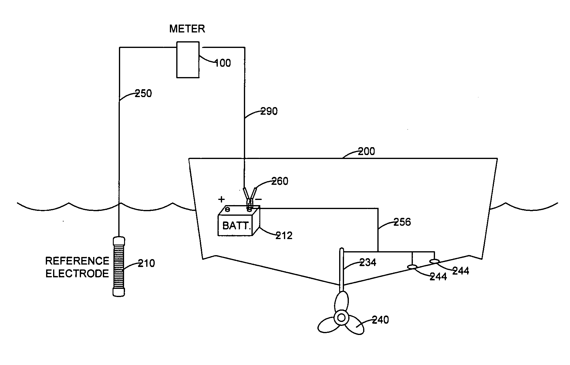
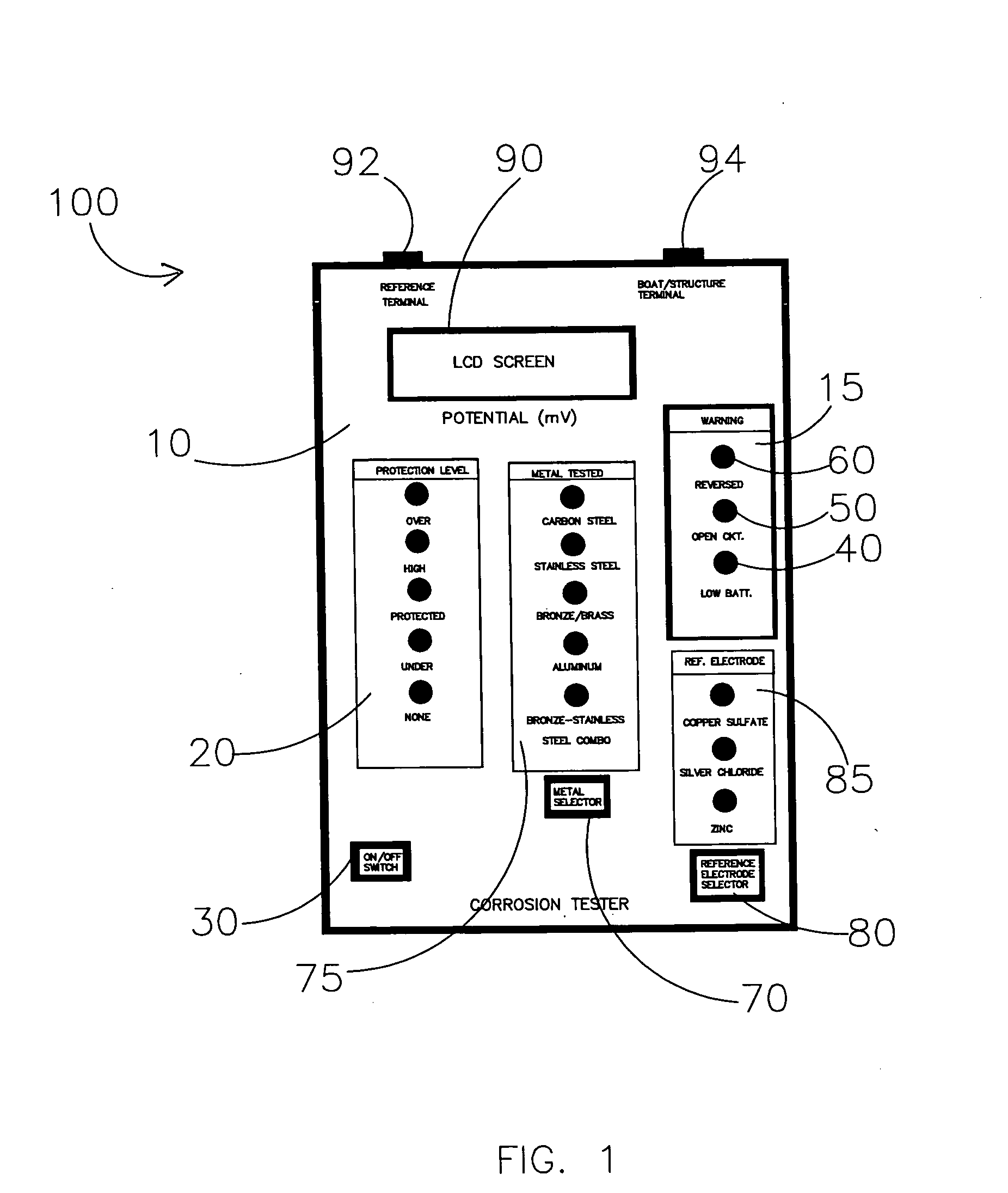
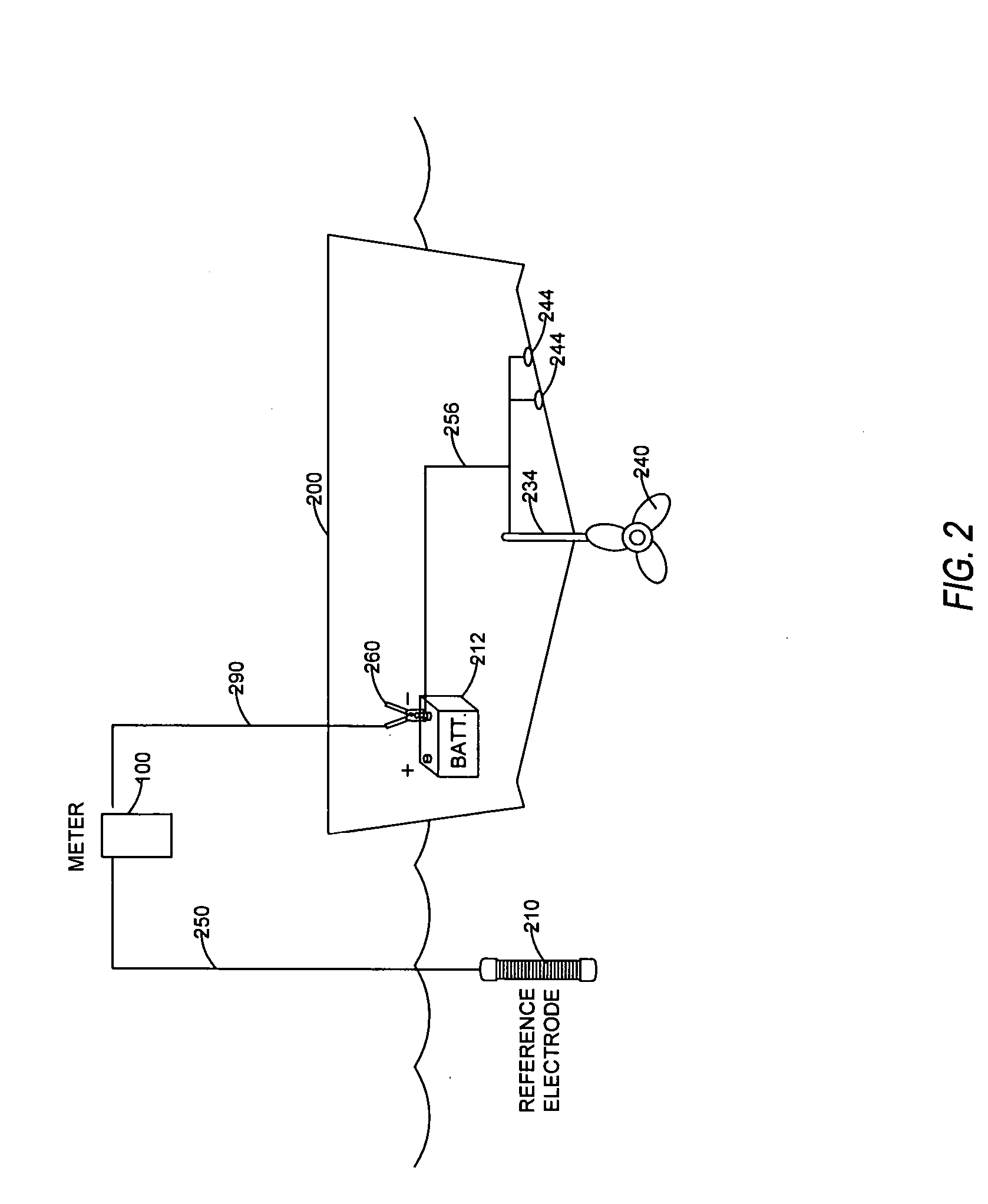
[0022] The present invention provides a handheld, cathodic protection system which collects and interprets the measurement data and indicates the level of protection being provided on the tested structure through the use of LED's on the front face of the meter panel. The device of the present invention is equipped with check status indicator signals to alert the operator to conditions that could result in erroneous measurements such as improper connections and low voltage power supply conditions. In this manner, erroneous readings such as those resulting from low voltage power supply to the meter are prevented.

[0023] The present invention further features proprietary circuitry to monitor either a DC waveform or a modified square waveform generated by a specific interrupted impressed current cathodic protection source. The meter captures the measurement of the potential reading during the time period that the current generated by the impressed current cathodic protection system is m...


PUM

PropertyMeasurementUnit
timeaaaaaaaaaa
marine corrosion testingaaaaaaaaaa
corrosionaaaaaaaaaa

Abstract

A portable, handheld, automatic protection level interpreting cathodic protection meter for testing the level of protection being afforded to metallic structures protected by either sacrificial anode or impressed current cathodic protection systems, or both. The meter is suitable over a variety of environments including salt water, freshwater, and soil. The operator can select both the type of metal to be tested as well as the type of reference electrode that is being used. The meter automatically calibrates data interpretation of the level of protection based on the operator's selections and eliminates any voltage drop error existing between a reference electrode and the structure being protected.

Description

CROSS-REFERENCES TO RELATED APPLICATIONS [0001] None. STATEMENT REGARDING FEDERALLY SPONSORED RESEARCH OR DEVELOPMENT [0002] None. REFERENCE TO A MICRO-FICHE APPENDIX [0003] None. BACKGROUND OF THE INVENTION Field of the Invention [0004] The present invention relates to a portable, handheld, automatic protection level interpreting cathodic protection monitoring device for testing the level of protection being afforded to metallic structures that are protected by either sacrificial anode or impressed current cathodic protection systems or combination of both. The apparatus of the present invention can be used for structures in a variety of environments including, but not limited to, salt water and freshwater applications as well as in soil applications. The present invention allows the operator to select both the type of metal to be tested from a range of metals programmed into the device as well as the type of reference electrode that is being utilized. The present invention automat...

Claims


Application Information

Patent Timeline
Patent Type & Authority Applications(United States)
IPC IPC(8): C23F13/00
CPCG01N17/02C23F13/04C23F13/22C23F2213/21C23F2213/31
Inventor HOWARD, J. DARBY JR.ALI, MOHAMMEDLISSON, CHRIS
Owner CALIFORNIA CORROSION CONCEPTS
Why Eureka
Try Eureka