Piezoelectric resonator, method for manufacturing the same, piezoelectric filter, and duplexer

a piezoelectric resonator and piezoelectric filter technology, applied in the piezoelectric/electrostrictive device material selection, device material selection, generator/motor, etc., can solve the problems of difficult stabilization of composition and complicated production process, and achieve the effect of improving the environmental resistance of excitation electrodes, improving the frequency temperature characteristics of piezoelectric resonators, and reducing variation in performan

Active Publication Date: 2006-03-30
MURATA MFG CO LTD
View PDF5 Cites 12 Cited by
  • Summary
  • Abstract
  • Description
  • Claims
  • Application Information

AI Technical Summary

Benefits of technology

[0021] When an insulating film is disposed to cover at least one excitation electrode of the pair of excitation electrodes, it becomes possible to improve the frequency temperature characteristics of the piezoelectric resonator and improve the environmental resistance of the excitation electrodes of the piezoelectric resonator.
[0022] The piezoelectric filter according to the present invention is constructed by including the piezoelectric resonator constructed according to the present invention and, therefore, a piezoelectric filter can be provided while variation in performance is reduced and the production process is simplified. In the case where the duplexer is constructed by including the piezoelectric resonator or the piezoelectric filter constructed according to the present invention as well, stabilization of the performance of the duplexer and cost reduction can be achieved.
[0023] The method for manufacturing a piezoelectric resonator according to the present invention includes the steps of forming the compound crystal by epitaxially growing the wurtzite structure compound crystal on the R-plane sapphire substrate having the (0,1,−1,2) crystal face parallel to the substrate surface in such a way that the (1,1,−2,0) crystal face becomes parallel to the substrate surface; forming the rectangular mask on the surface, which is the (1,1,−2,0) crystal face of the compound crystal, in parallel to the C plane which is the (0,0,0,1) crystal face of the piezoelectric material; dry-etching the compound crystal after the mask is formed, so as to form the tabular piezoelectric material made of the compound crystal; and forming the pair of excitation electrodes on the pair of principal surfaces opposite to each other in the thickness direction of the piezoelectric material in such a way that the pair of excitation electrodes sandwich the C plane which is the (0,0,0,1) crystal face perpendicular to the (1,1,−2,0) crystal face of the piezoelectric material. Consequently, the piezoelectric resonator of the present invention can readily be produced by undergoing the above-described epitaxial growth and dry-etching.

Problems solved by technology

Since the PZT piezoelectric ceramic contains three elements, Pb, Ti and Zr, as metal atoms, there is a problem in that the composition is hard to stabilize.
Consequently, the production process is complicated.

Method used


Image

  • Piezoelectric resonator, method for manufacturing the same, piezoelectric filter, and duplexer
  • Piezoelectric resonator, method for manufacturing the same, piezoelectric filter, and duplexer
  • Piezoelectric resonator, method for manufacturing the same, piezoelectric filter, and duplexer

Examples


first embodiment

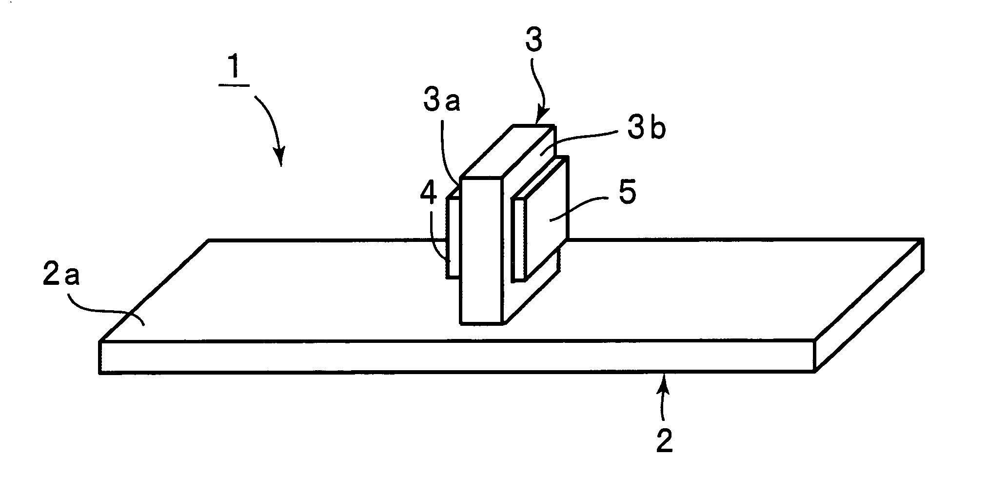
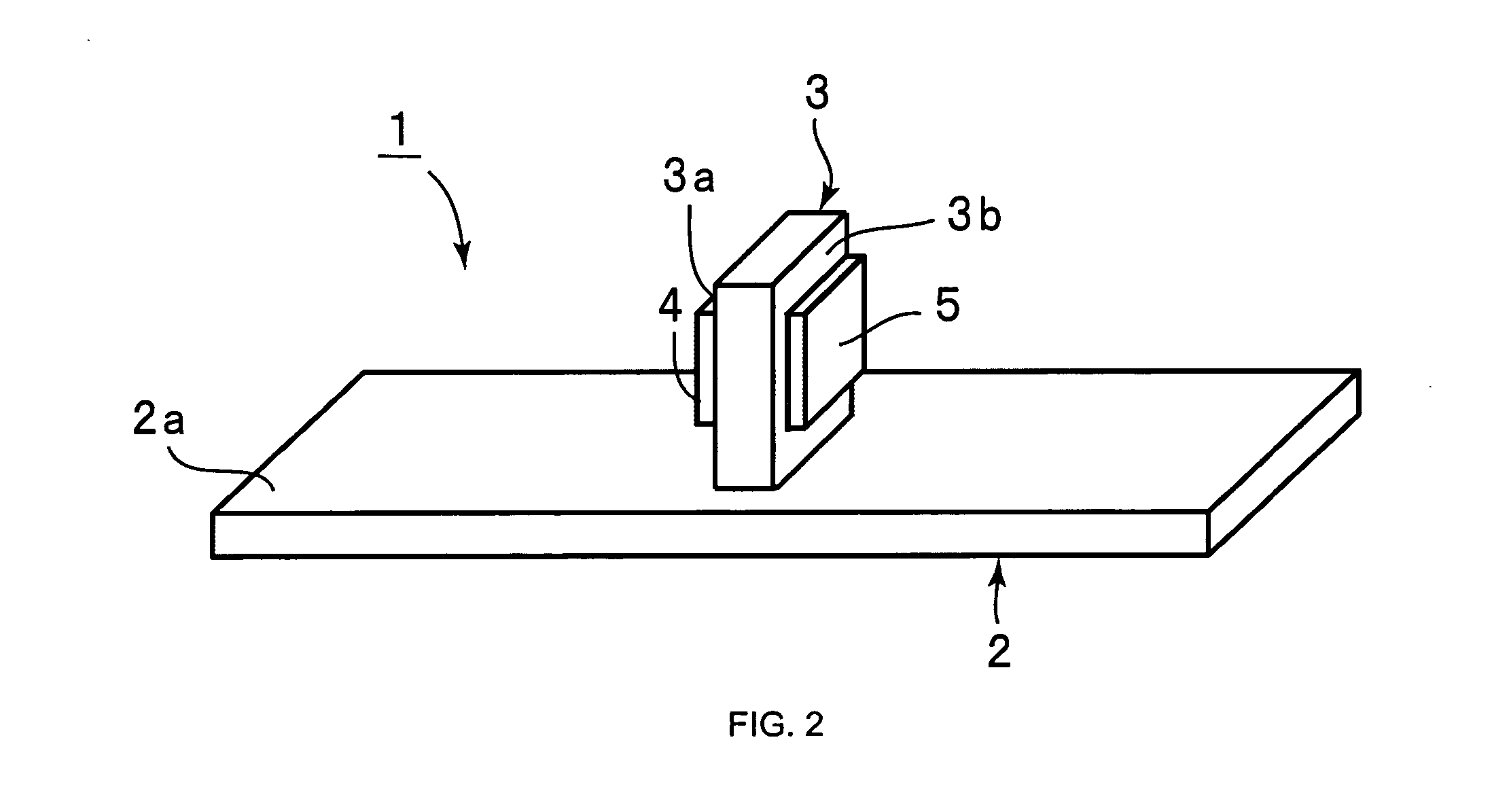
[0036]FIG. 2 is a perspective view showing a piezoelectric resonator according to the present invention. A piezoelectric resonator 1 includes an R-plane sapphire substrate 2. The top surface 2a of the R-plane sapphire substrate 2 is the R-plane, that is, a (0,1,−1,2) crystal face. In the present embodiment, a rectangular plate-shaped piezoelectric plate 3 made of a compound single crystal primarily containing ZnO is disposed upright on the top surface 2a of the R-plane sapphire substrate 2. This piezoelectric plate 3 is formed by patterning a compound crystal epitaxially grown on the R-plane sapphire substrate, as described below. A (1,1,−2,0) crystal face of the piezoelectric plate 3 is made parallel to the (0,1,−1,2) crystal face which is the top surface of the sapphire substrate 2. Therefore, when an alternating-current voltage is applied in between a pair of principal surfaces 3a and 3b opposite to each other in the thickness direction of the piezoelectric plate 3, resonant char...

second embodiment

[0051]FIG. 5 is a perspective view showing a piezoelectric resonator according to the present invention. In this piezoelectric resonator 11, a plurality of piezoelectric plates 13 to 16 are disposed upright on the top surface 12a of one R-plane sapphire substrate 12. Pairs of excitation electrodes 17a, 17b to 20a, 20b are disposed on pairs of surfaces 13a, 13b to 16a, 16b, respectively, opposite to each other in the thickness direction of the piezoelectric plates 13 to 16, respectively.

[0052] The piezoelectric plates 13 to 16 are disposed similarly to the piezoelectric plate 3 of the first embodiment.

[0053] That is, a plurality of piezoelectric resonant units 13A to 16A corresponding to the piezoelectric resonator 1 shown in FIG. 1 are integrally constructed on one R-plane sapphire substrate 12 in the piezoelectric resonator 11 of the second embodiment. The piezoelectric resonant units 13A to 16A are electrically connected in parallel as schematically shown in FIG. 5.

[0054] Accord...

third embodiment

[0068]FIG. 9 is a perspective view showing a piezoelectric resonator according to the present invention.

[0069] In a piezoelectric resonator 31, as in the first embodiment, piezoelectric plates 33 and 34 made of a wurtzite type crystal primarily containing ZnO are disposed upright on an R-plane sapphire substrate 32. Excitation electrodes 35, 36, 37, 38, and 39 are disposed on respective surfaces of a pair of surfaces of the piezoelectric plate 33 and a pair of surfaces of the piezoelectric plate 34 opposite to each other in the thickness direction of the piezoelectric plates 33 and 34. Here, the excitation electrodes 35 and 36 are disposed with a gap therebetween on the principal surface 33a of the piezoelectric plate 33. The excitation electrode 37 is disposed on the principal surface 33b opposite to the principal surface 33a. The excitation electrode 37 is opposite to the excitation electrodes 35 and 36 with the piezoelectric plate 33 therebetween. The excitation electrode 37 is e...


PUM


Abstract

A piezoelectric resonator suitable for use in a high frequency band is provided, in which variation in the piezoelectric material is reduced, variation in performance is reduced, and production can be performed without the need for a polarization treatment step. In the piezoelectric resonator, a piezoelectric material made of a wurtzite structure compound crystal is disposed, the crystal epitaxially grown in such a way that a (1,1,−2,0) crystal face becomes parallel to a surface of the R-plane sapphire substrate having a (0,1,−1,2) crystal face parallel to the substrate surface, and a pair of excitation electrodes are disposed on a pair of principal surfaces opposite to each other in the thickness direction of the piezoelectric material in such a way that the pair of excitation electrodes sandwich the C plane which is a (0,0,0,1) crystal face perpendicular to the (1,1,−2,0) crystal face of the tabular piezoelectric material.

Description

BACKGROUND OF THE INVENTION [0001] 1. Field of the Invention [0002] The present invention relates to a piezoelectric resonator which takes advantage of thickness longitudinal vibration. In particular, the present invention relates to a piezoelectric resonator having a structure in which a tabular piezoelectric material with a pair of excitation electrodes disposed on a pair of principal surfaces stands upright on a substrate, as well as a method for manufacturing the same, a piezoelectric filter including the piezoelectric resonator, and a duplexer. [0003] 2. Description of the Related Art [0004] In recent years, as the frequencies of communications equipment haveincreased, various piezoelectric resonators and piezoelectric filters taking advantage of thin piezoelectric materials and piezoelectric thin films have been proposed. For example, FIG. 1 is a perspective view partially showing a piezoelectric resonator disclosed in Japanese Unexamined Patent Application Publication No. 200...

Claims


Application Information

Patent Timeline
Patent Type & Authority Applications(United States)
IPC IPC(8): H01L41/18H01L41/09H01L41/187H01L41/22H01L41/314H01L41/319H01L41/332H03H3/02H03H3/04H03H9/02H03H9/17H03H9/19H03H9/58H03H9/60H03H9/70
CPCH03H3/04H03H9/02102H03H9/02157H03H9/605H03H9/176H03H9/60H03H9/172H03H3/02H03H9/17H03H9/205
Inventor YAMADA, HAJIME
Owner MURATA MFG CO LTD
Why Eureka
Try Eureka