Retractable storage system

a storage system and movable technology, applied in the direction of dressing tables, movable shelf cabinets, cabinets, etc., can solve the problems of requiring unobstructed space both laterally and downwardly of the mobile storage organizer, preventing full utilization of the area positioned and requiring unobstructed space below the movable storage organizer

Inactive Publication Date: 2006-03-30
CRAWFORD JOHN D
View PDF17 Cites 60 Cited by
  • Summary
  • Abstract
  • Description
  • Claims
  • Application Information

AI Technical Summary

Benefits of technology

[0009] In an advantage provided by this invention, a retractable storage system is provided which is of a lightweight, low-cost manufacture.

Problems solved by technology

One drawback associated with such devices, however, is that they prevent full utilization of the area positioned below the movable storage organizer.
Unless the ceilings are extraordinarily high or the movable storage organizer extraordinarily small, the space below the movable storage organizer would be too small for a person to walk below.
Another drawback associated with such movable storage organizers is that they require unobstructed space both laterally and downwardly of the mobile storage organizer.
Yet another drawback of such systems is that they require additional unobstructed space above the movable storage organizer which cannot be utilized.
Most notably, the Hughes device is designed for moving large objects and, therefore, does not provide any means for storing a large number of small objects, such as files or the like.
Still another drawback associated with Hughes is the utilization of telescopic arms which require large vertical members to extend far beyond the uppermost portion of the elevator.
Still another drawback associated with the Hughes is the inability to control the flow of air from the top floor to the bottom floor.
In a situation, such as a home use, where the device may be desired to be used between a living area and an attic, the Hughes device would allow moisture and heat to flow between the two areas, and would not insulate any material provided on the platform from damage associated with climatic conditions in an attic.
Still another drawback associated with the Hughes device is the lack of safety devices to warn individuals of the moving platform, or to prevent the moving platform from contacting, and injuring or killing, a user.

Method used


Image

  • Retractable storage system
  • Retractable storage system
  • Retractable storage system

Examples


Embodiment Construction

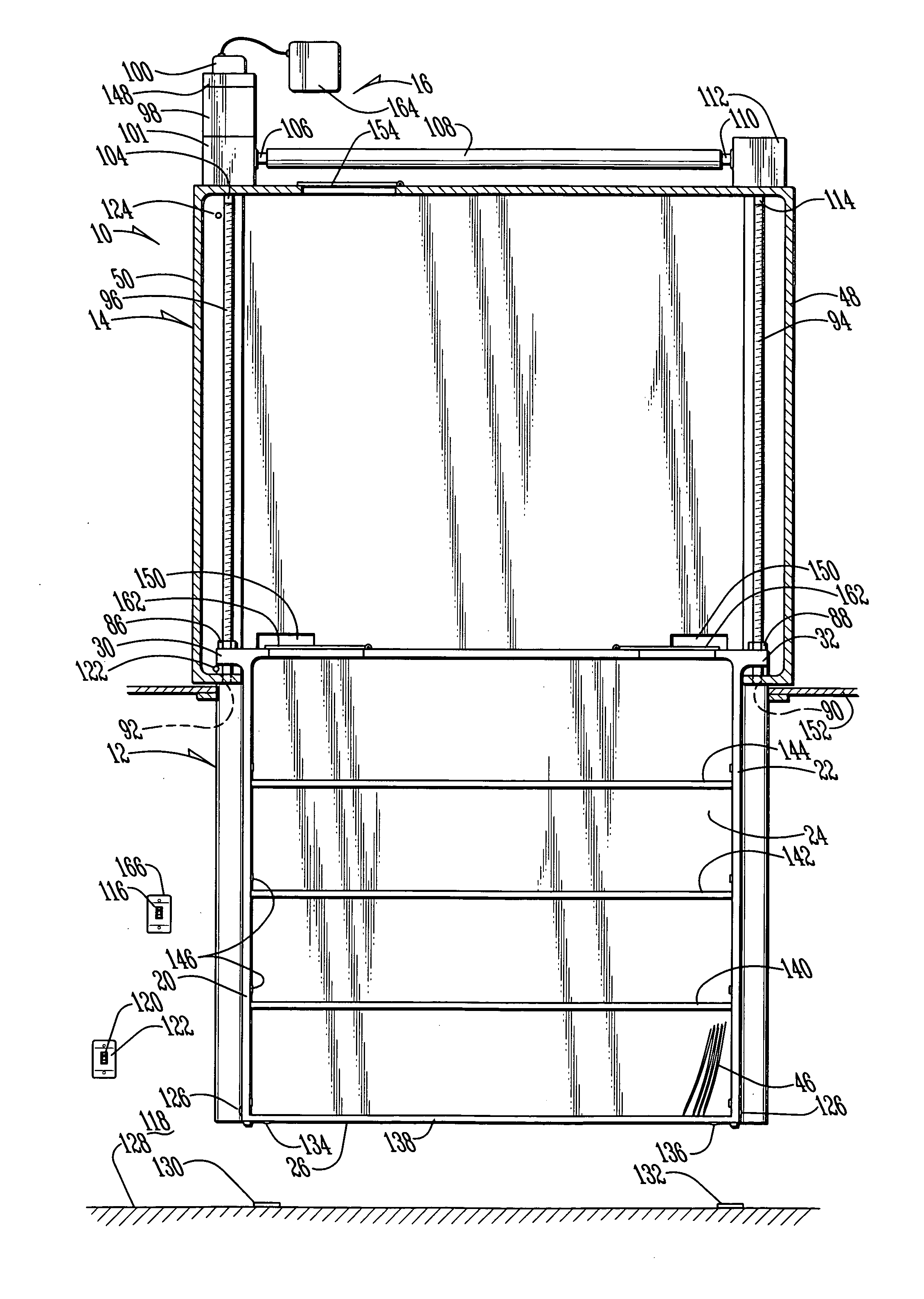
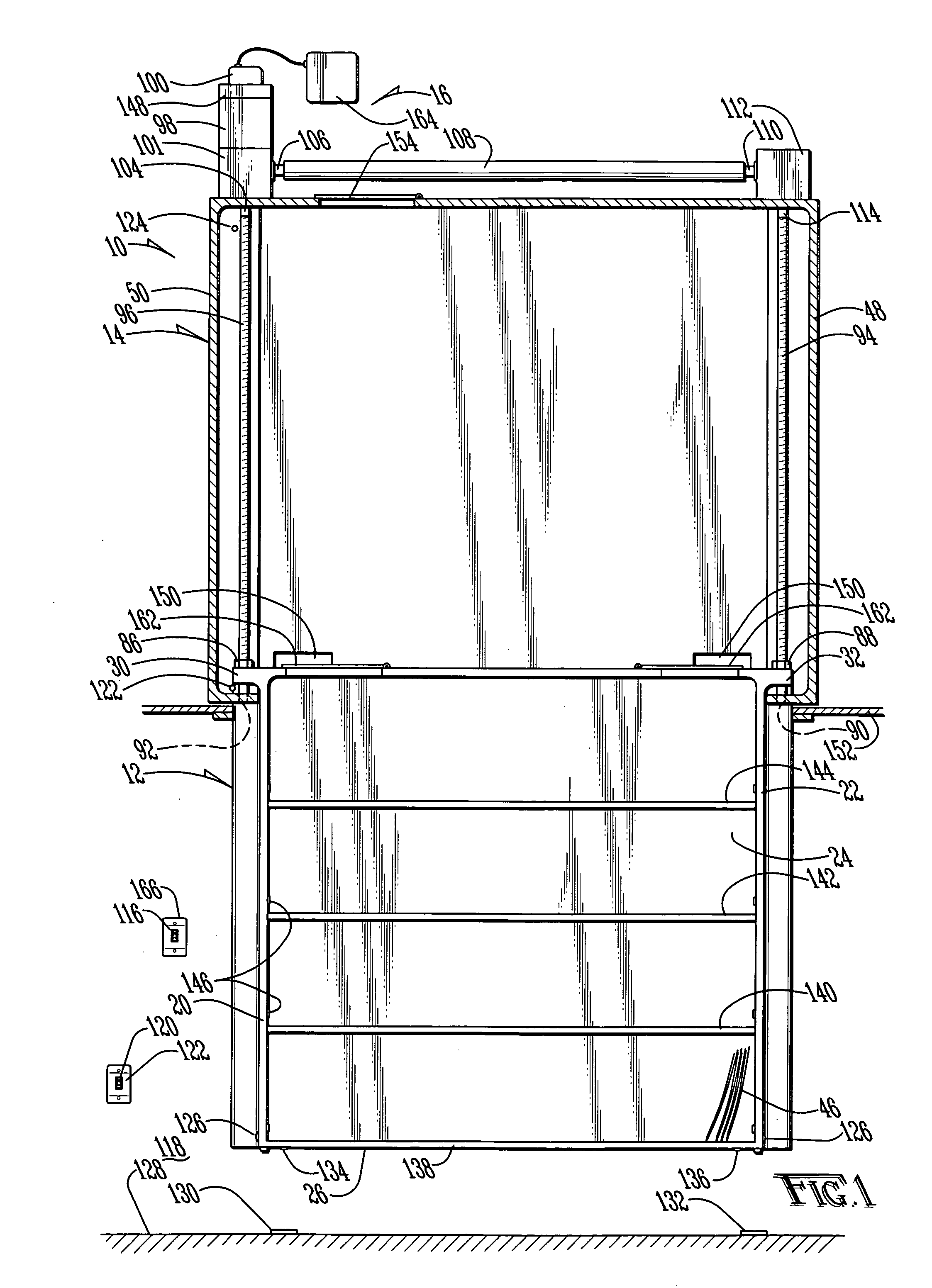
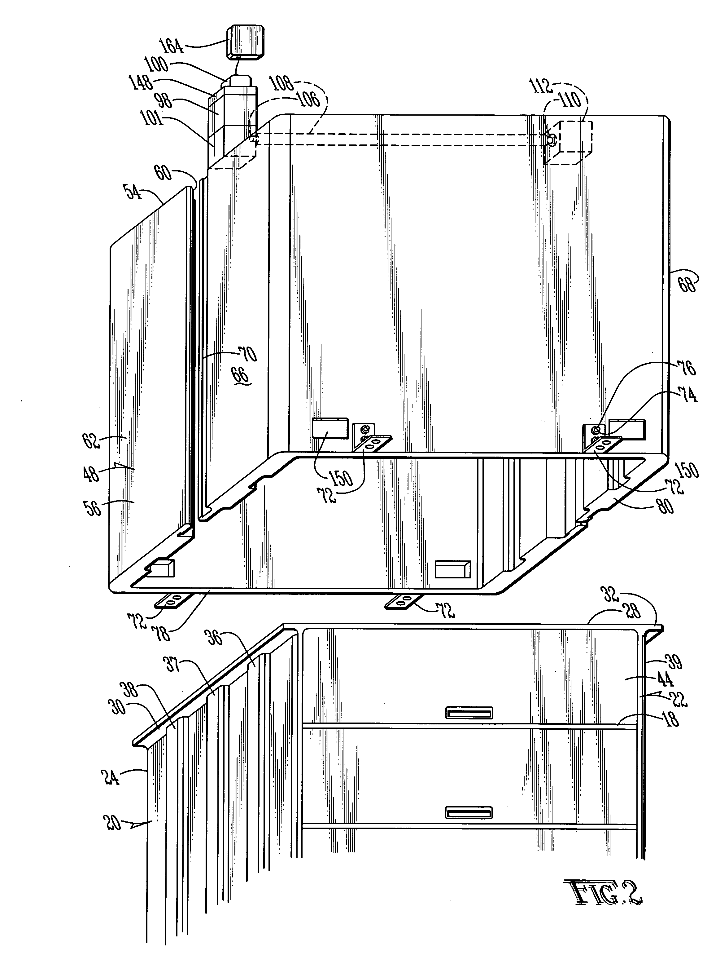
[0024] A retractable storage system according to the present invention is shown generally as (10) in FIG. 1. The retractable storage system (10) includes a multi-tiered rack, which in the preferred embodiment is a set of shelves (12), an enclosure (14) and a lift system (16). As shown in FIGS. 1-2, the set of shelves (12) is injection molded or rotomolded in a manner such as that known in the art. In the preferred embodiment the set of shelves (12) is injection molded of a copolymer of polypropylene and polyethylene. Of course, the set of shelves may be injection molded of nylon or any other desired material, or may be constructed using wood, metal or any other material known in the art for construction of such shelves. The set of shelves (12) is preferably molded with a face (18), a first side (20), a second side (22) a back (24), a bottom (26) and a top (28). Each side (20) and (22) is provided with three tongues (36), (37), (38) and (39), (40), (41) integrally molded as part of t...


PUM


Abstract

The system includes an enclosure provided upward through a hole provided in a ceiling. The enclosure includes a motor for lifting a set of shelves into the enclosure. The enclosure protects the set of shelves and its contents from moisture and heat, and prevents heat and moisture from escaping from one room to another, across the enclosure. The system is designed to allow installation of the entire system from the lower level, without requiring access to the upper level.

Description

BACKGROUND OF THE INVENTION [0001] 1. Field of the Invention [0002] The present invention relates in general to retractable storage systems and, more particularly, to storage systems which retract into a ceiling. [0003] 2. Description of the Prior Art [0004] It is well known in the art to provide retractable storage systems. One such system is shown in U.S. Pat. No. 5,758,782 to Rupert. The system shows a movable storage organizer which may be provided in a closet or the like to utilize space above hanging clothes or the like. One drawback associated with such devices, however, is that they prevent full utilization of the area positioned below the movable storage organizer. Unless the ceilings are extraordinarily high or the movable storage organizer extraordinarily small, the space below the movable storage organizer would be too small for a person to walk below. [0005] Additionally, Rupert teaches the utilization of a parallel linkage system to extend the movable storage organizer...

Claims


Application Information

Patent Timeline
Patent Type & Authority Applications(United States)
IPC IPC(8): A47B67/02
CPCE04B9/003A47B51/00
Inventor CRAWFORD, JOHN D.
Owner CRAWFORD JOHN D
Why Eureka
Try Eureka