Motor driving apparatus

Active Publication Date: 2006-03-30
FANUC LTD
View PDF10 Cites 21 Cited by
  • Summary
  • Abstract
  • Description
  • Claims
  • Application Information

AI Technical Summary

Benefits of technology

[0010] In view of the above problems, it is an object of the present invention to provide a motor driving apparatus that can improve efficiency by using the energy stored in a power storage means connected with a DC link part.
[0011] It is a further object of the present invention to provide

Problems solved by technology

Therefore, in order to perform maintenance work of the motor driving apparatus having the power storage means of such large capacitance, there is a problem in that an operator is forced to perform the maintenance work in an environment where hazardous voltage exists (in an environment where an enormous amount of energy exists) and the safety of the operator i

Method used


Image

  • Motor driving apparatus
  • Motor driving apparatus
  • Motor driving apparatus

Examples


first embodiment

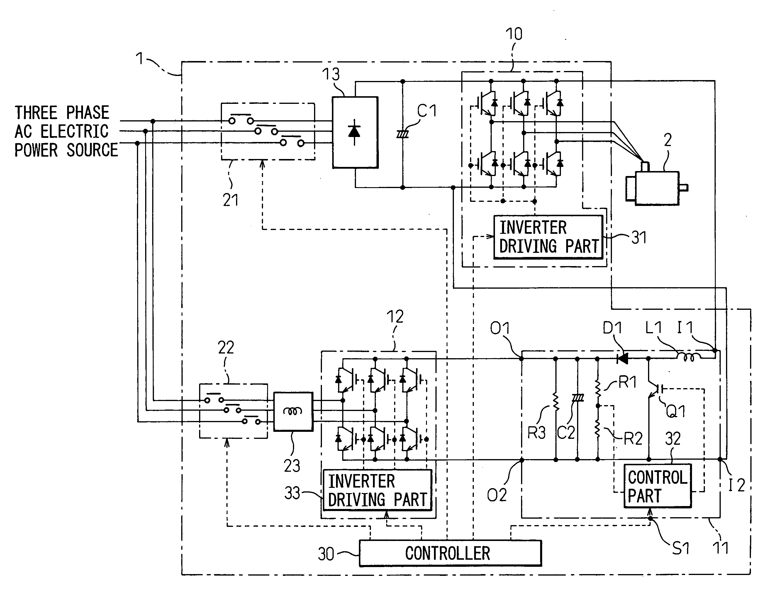
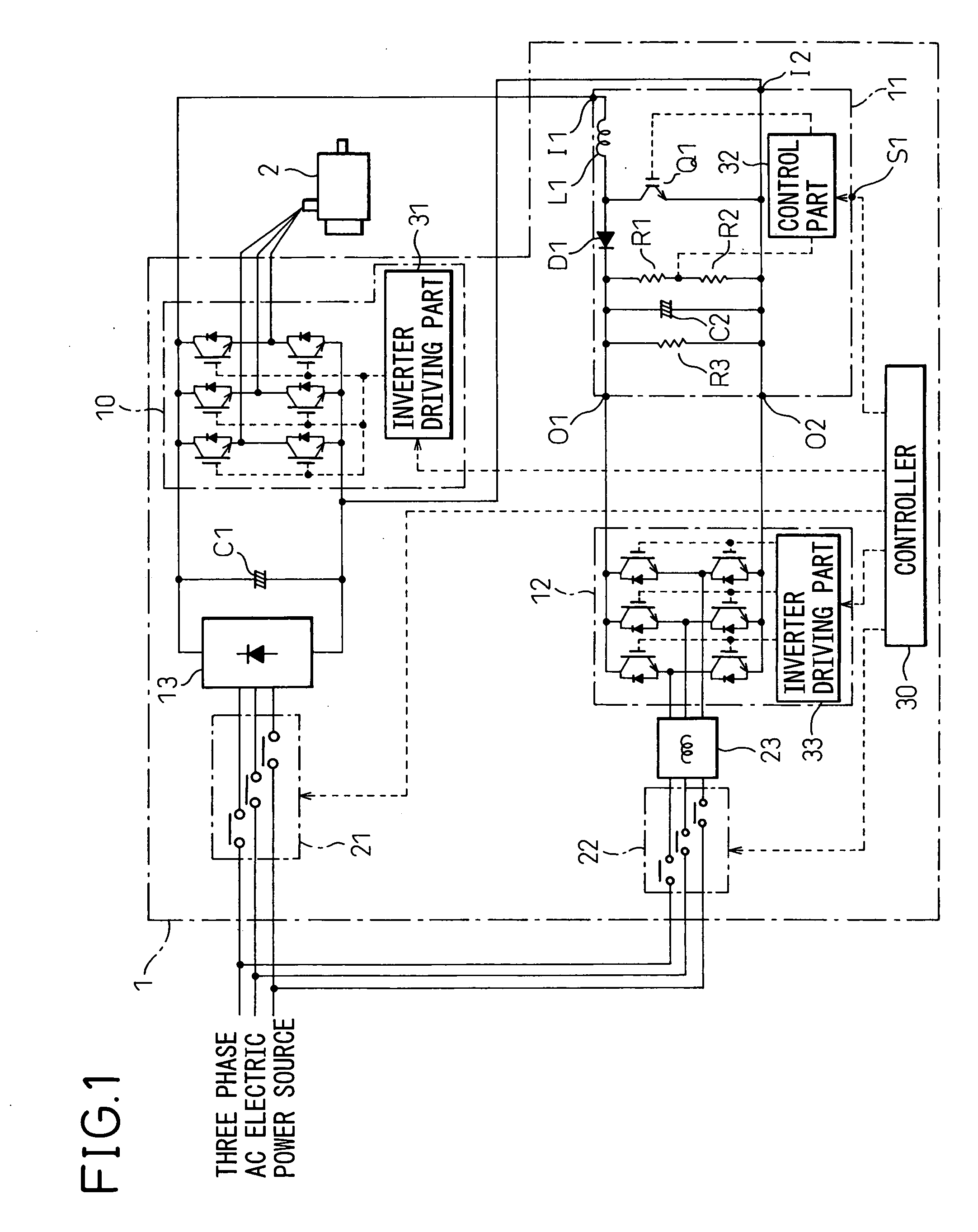
[0022] Hereinafter, preferred embodiments of the present invention will be described in detail with reference to the accompanying drawings. FIG. 1 is a block diagram of a motor driving apparatus of the present invention. In the circuit block diagrams shown in FIGS. 1 and 3 to 5, electric power lines for supplying electric power to drive a motor are designated by solid lines, whereas control lines such as signal lines are designated by dotted lines.

[0023] As shown in the figures, a motor driving apparatus 1 includes a power source rectifier circuit 13 for converting AC electric power supplied from a three-phase AC power source into DC electric power, and an inverter circuit 10 for converting this DC electric power into AC electric power of variable voltage and variable frequency to be supplied to the motor 2, wherein the power source rectifier circuit 13 is connected with the inverter circuit 10 via a DC link.

[0024] The power source rectifier circuit 13 may be constituted, for examp...

second embodiment

[0044]FIG. 3 is a block diagram of a motor driving apparatus according to the present invention. The exemplary motor driving apparatus 1 shown in FIG. 3 includes a converter circuit 14 that acts as a power source rectifier circuit to perform regeneration. Then, the DC link is provided between the converter circuit 14 and the inverter circuit 10 to transfer the DC electric power, rectified from the three-phase AC electric power by the converter circuit 14, to the inverter circuit 10.

[0045] The converter circuit 14 is constituted by a bridge circuit including power devices (such as transistors, for example) and diodes connected in anti-parallel with these power devices. Then, during normal power operation of the motor 2, the diodes perform full-wave rectification of AC electric power supplied from the three-phase AC power source to convert it into DC electric power.

[0046] On the other hand, during regeneration of the motor 2, when the link voltage divided by the resistors R7 and R8 e...

third embodiment

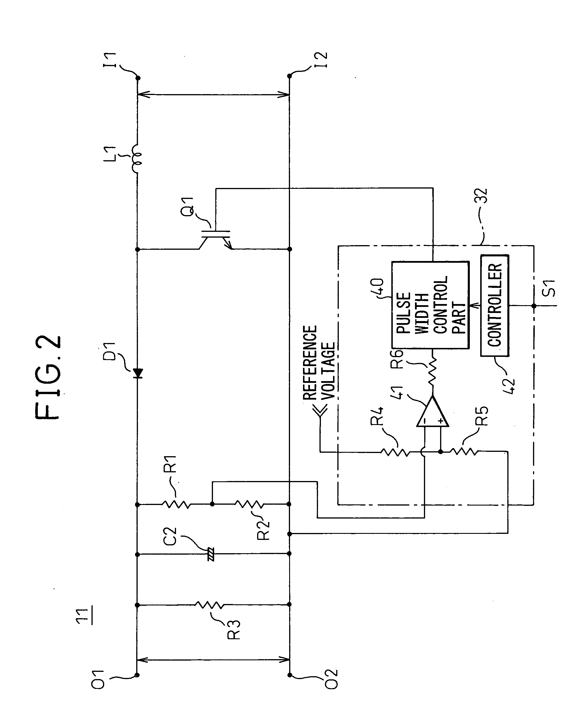
[0050]FIG. 4 is a block diagram of a motor driving apparatus according to the present invention. As shown in FIG. 4, the motor driving apparatus 1 includes the converter circuit 14 shown in FIG. 3 that is configured to perform regeneration, the inverter circuit 10 that converts DC electric power into AC electric power and supplies it to the motor 2, and the DC link that connects the converter circuit 14 with the inverter circuit 10 and, similarly to that shown in FIG. 1, the motor driving apparatus 1 is provided with the step-up type DC / DC converter circuit 11, the AC inverter circuit 12, the electromagnetic connector 21 for connecting / disconnecting AC main input, and the electromagnetic connector 22 for connecting / disconnecting AC input to the regeneration inverter.

[0051] The step-up type DC / DC converter circuit 11, the input terminals of which are connected to the DC link, boosts the DC link voltage as described above and outputs it to the AC inverter circuit 12. Then, the AC inve...


PUM


Abstract

The present invention is directed to the provision of a servomotor driving apparatus that feeds energy stored in a power storage part connected with a DC link that connects a rectifier circuit with an inverter circuit so that the energy stored in the power storage part can be reduced. A motor driving apparatus (1) includes: a step-up type DC/DC converter circuit (11) for boosting voltage appearing at an output of the power storage part (C1) connected with a DC link; and a DC/AC conversion circuit (12, 14) for converting the boosted DC electric power into AC electric power and feeding it to an electric power source.

Description

BACKGROUND OF THE INVENTION [0001] 1. Field of the Invention [0002] The present invention relates to a motor driving apparatus and, more particularly, it relates to a motor driving apparatus that feeds electric power, stored during regeneration, to an electric power source. [0003] 2. Description of the Related Art [0004] In a motor driving apparatus, a large driving current flows during normal power operation and a regenerative current flows during deceleration. Therefore, the motor driving apparatus has to be designed in consideration of the peak current during normal power operation and, as a result, it is forced to be large in size and expensive. Further, the regenerative current generated during deceleration is fed to a resistor so that it is transformed into thermal energy and consumed and, therefore, the energy is wastefully lost. [0005] As a measure to solve these problems, a motor driving apparatus disclosed in Japanese Unexamined Patent Publication No. 2000-141440 includes ...

Claims


Application Information

Patent Timeline
IPC IPC(8): H02P27/04H02P3/18
CPCH02M5/4585H02M7/53875H02P3/18H02M1/008
Inventor OTA, NAOTOKONO, SHINICHIYAESHIMA, MAMORUYAMADA, YUUICHI
Owner FANUC LTD
Why Eureka
Try Eureka