Energy recovery apparatus and method of a plasma display panel

Inactive Publication Date: 2006-03-30
LG ELECTRONICS INC
View PDF3 Cites 5 Cited by
  • Summary
  • Abstract
  • Description
  • Claims
  • Application Information

AI Technical Summary

Benefits of technology

[0026] According to the present invention, energy is relayed between a source capacitor and a panel capac

Problems solved by technology

However, a large amount of manufacturing cost is required in order to fabricate this conventional energy recovery apparatus.
Therefore, s

Method used


Image

  • Energy recovery apparatus and method of a plasma display panel
  • Energy recovery apparatus and method of a plasma display panel
  • Energy recovery apparatus and method of a plasma display panel

Examples


Embodiment Construction

[0035] Preferred embodiments of the present invention will be described in a more detailed manner with reference to the drawings.

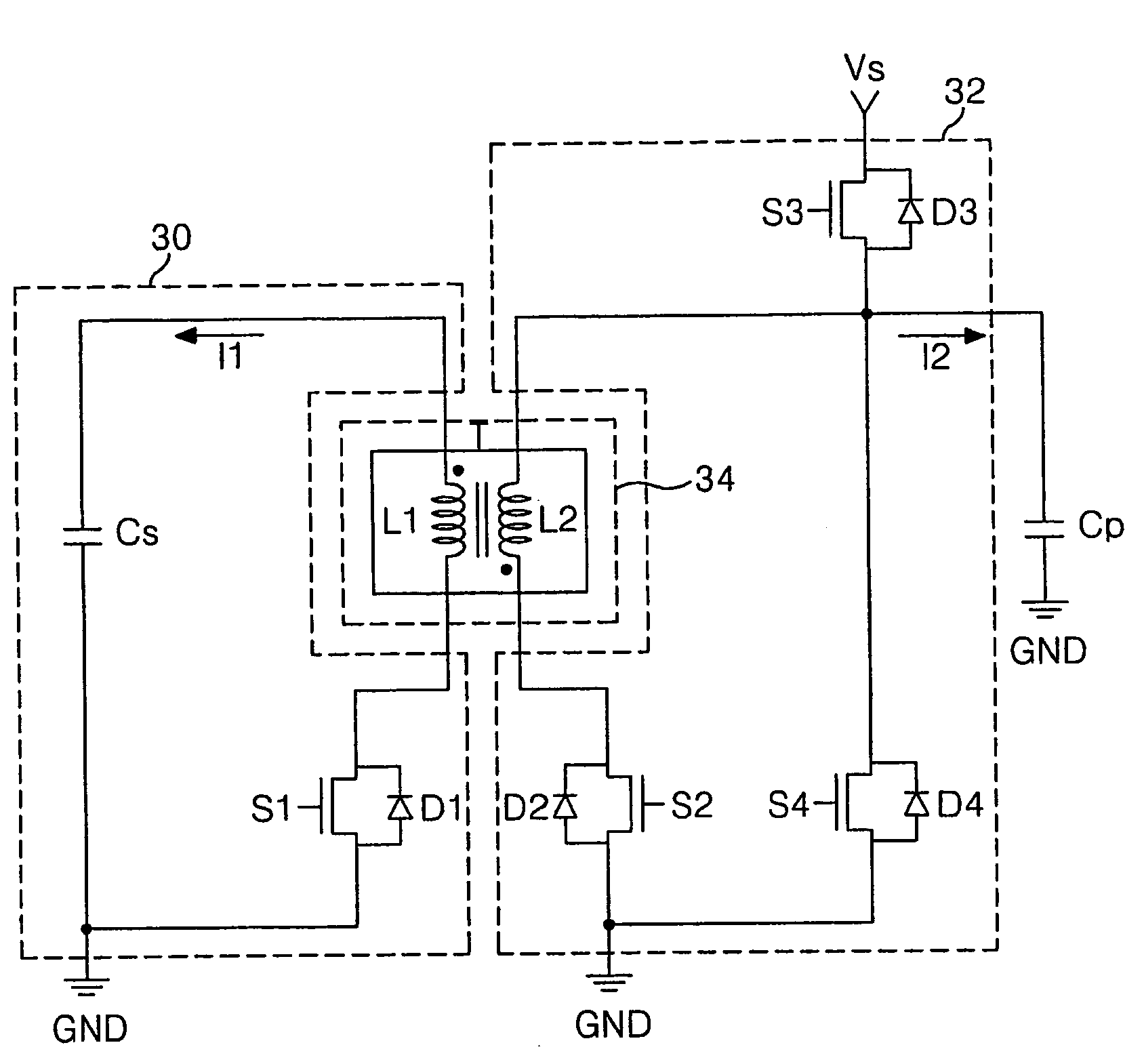
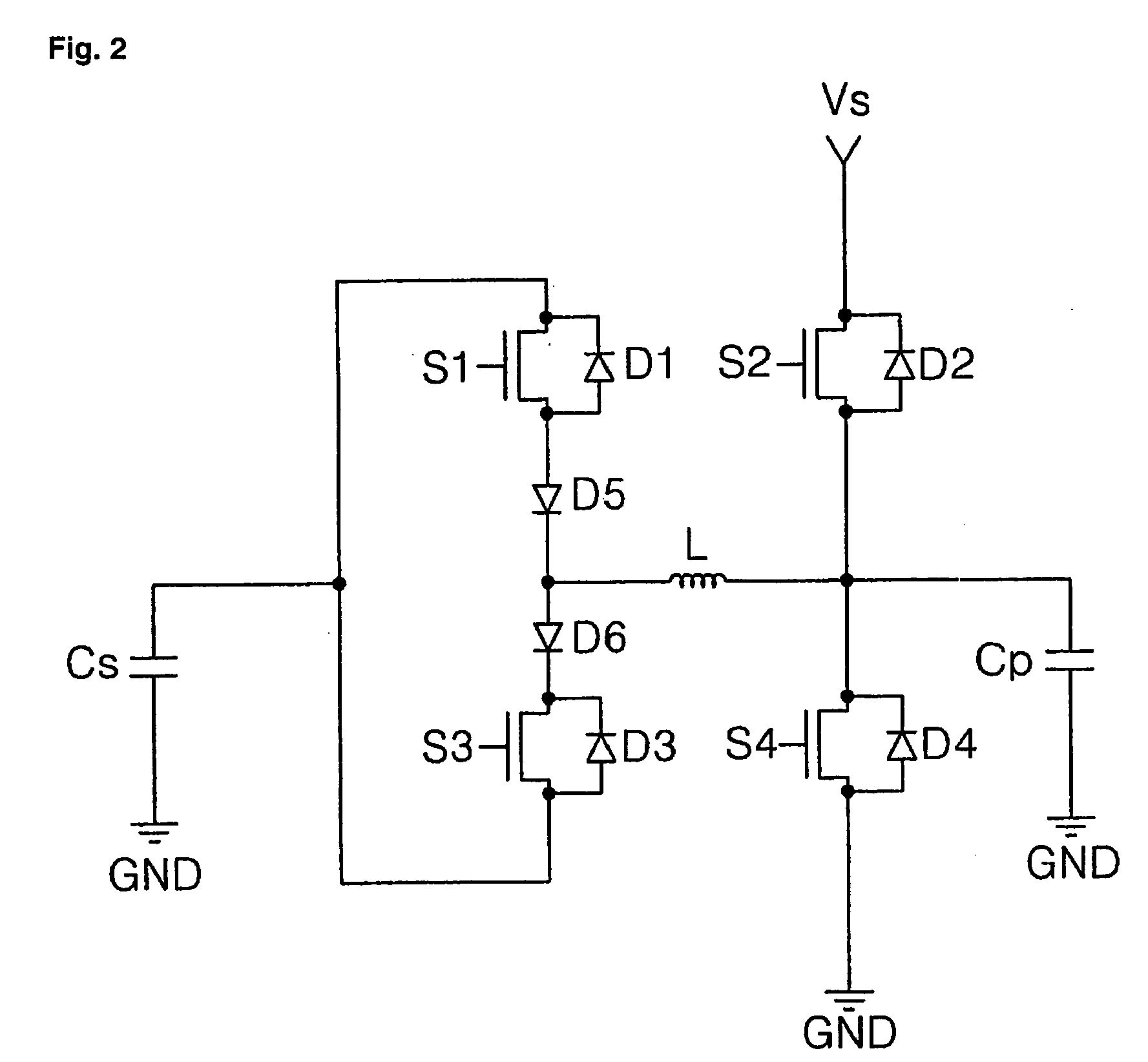
[0036] To achieve the above object, according to one aspect of the present invention, there is provided an energy recovery apparatus, including a capacitive load equivalently formed between a scan electrode and a sustain electrode, an energy recovery unit for recovering energy charged in the capacitive load and again supplying the recovered energy to the capacitive load, an energy supply unit disposed between the energy recovery unit and the capacitive load, wherein the energy supply unit relays energy between the energy recovery unit and the capacitive load and supplies a reference voltage to the capacitive load so that stabilized discharging can be generated in the capacitive load, and an energy relay unit disposed between the energy recovery unit and the energy supply unit, for relaying energy between the energy recovery unit and the energy supply unit...


PUM


Abstract

The present invention relates to a plasma display panel, and more particularly, to an energy recovery apparatus of a plasma display panel and method thereof. The energy recovery apparatus includes a capacitive load equivalently formed between a scan electrode and a sustain electrode, an energy recovery unit for recovering energy charged in the capacitive load and again supplying the recovered energy to the capacitive load, an energy supply unit disposed between the energy recovery unit and the capacitive load, wherein the energy supply unit relays energy between the energy recovery unit and the capacitive load and supplying a reference voltage to the capacitive load so that stabilized discharging can be generated in the capacitive load, and an energy relay unit disposed between the energy recovery unit and the energy supply unit, for relaying energy between the energy recovery unit and the energy supply unit. According to the present invention, energy is relayed between a source capacitor and a panel capacitor through a transformer. Therefore, diodes need not to be used and manufacturing cost is thus reduced.

Description

BACKGROUND OF THE INVENTION [0001] 1. Field of the Invention [0002] The present invention relates to a plasma display panel, and more particularly, to an energy recovery apparatus of a plasma display panel and method thereof. [0003] 2. Description of the Background Art [0004] A plasma display panel (hereinafter, referred to as a ‘PDP’) is adapted to display an image including characters or graphics by light-emitting phosphors with ultraviolet having a wavelength of 147 nm generated during the discharge of an inert mixed gas such as He+Xe, Ne+Xe or He+Ne+Xe. This PDP can be easily made thin and large, and it can provide greatly increased image quality with the recent development of the relevant technology. Particularly, a three-electrode AC surface discharge type PDP has advantages of lower driving voltage and longer product lifespan as a wall charge is accumulated on a surface in discharging and electrodes are protected from sputtering caused by discharging. [0005]FIG. 1 is a perspe...

Claims


Application Information

Patent Timeline
IPC IPC(8): G09G5/00
CPCG09G3/2965
Inventor YOO, JI SEUNG
Owner LG ELECTRONICS INC
Why Eureka
Try Eureka