Arc extinguishing stab housing and method

Active Publication Date: 2006-03-30
ROCKWELL AUTOMATION TECH
View PDF14 Cites 60 Cited by
  • Summary
  • Abstract
  • Description
  • Claims
  • Application Information

AI Technical Summary

Benefits of technology

[0011] The present technique is designed to respond to such needs. The technique, applicable to low voltage, medium voltage, and high voltage power management systems, provides for substantially containing and directing an arcing fault and resultant ionized gases within a stab enclosure or housing disposed, for example, in an MCC. The stab housing may have reduced stab-openings at the power bus interface to diminish the potential of an arc flash (and ionized gases) from reaching the power buses. Furthermore, the stab housing may employ phase-to-phase isolation barriers to reduce the potential of an arcing fault propagating from one phase to another. Moreover, to reduce arc flash damage within th

Problems solved by technology

Systems that distribute electrical power for residential, commercial, and industrial uses can be complex and widely divergent in design and operation.
A problem in the operation of MCCs and other power management systems, such as switchboards and panelboards, is the occurrence of arcing (also called an arc, arc fault, arcing fault, arc flash, arcing flash, etc.) which may be thought of as an electrical conduction or short circuit through gas or air.
Initiation of an arc fault may be caused by a momentary or loose connection, build-up of foreign matter such as dust or dirt mixed with moisture, insulation failure, or a short-circuit (e.g., a foreign object establishing an unwanted connection between phases or from a phase to ground) which causes the arc to be drawn, and so forth.
On the other hand, arcing faults may be intermittent failures between phases or phase-to-ground, and may be discontinuous currents that alternately strike, extinguish, and strike again.
In either case, the result is an intense thermal event (e.g., temperatures up to 35,000° F.) causing melting and vapor

Method used


Image

  • Arc extinguishing stab housing and method
  • Arc extinguishing stab housing and method
  • Arc extinguishing stab housing and method

Examples


Embodiment Construction

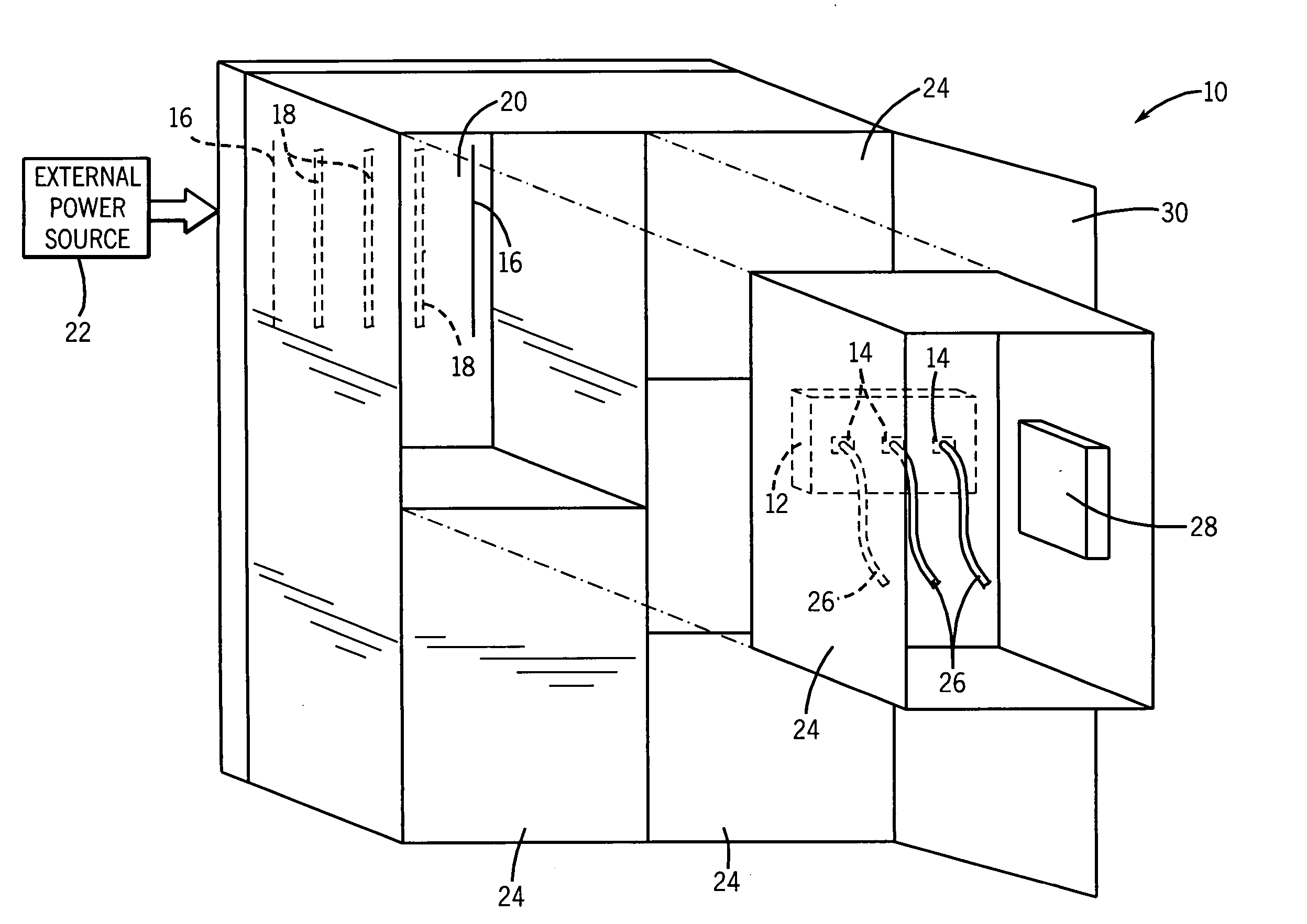
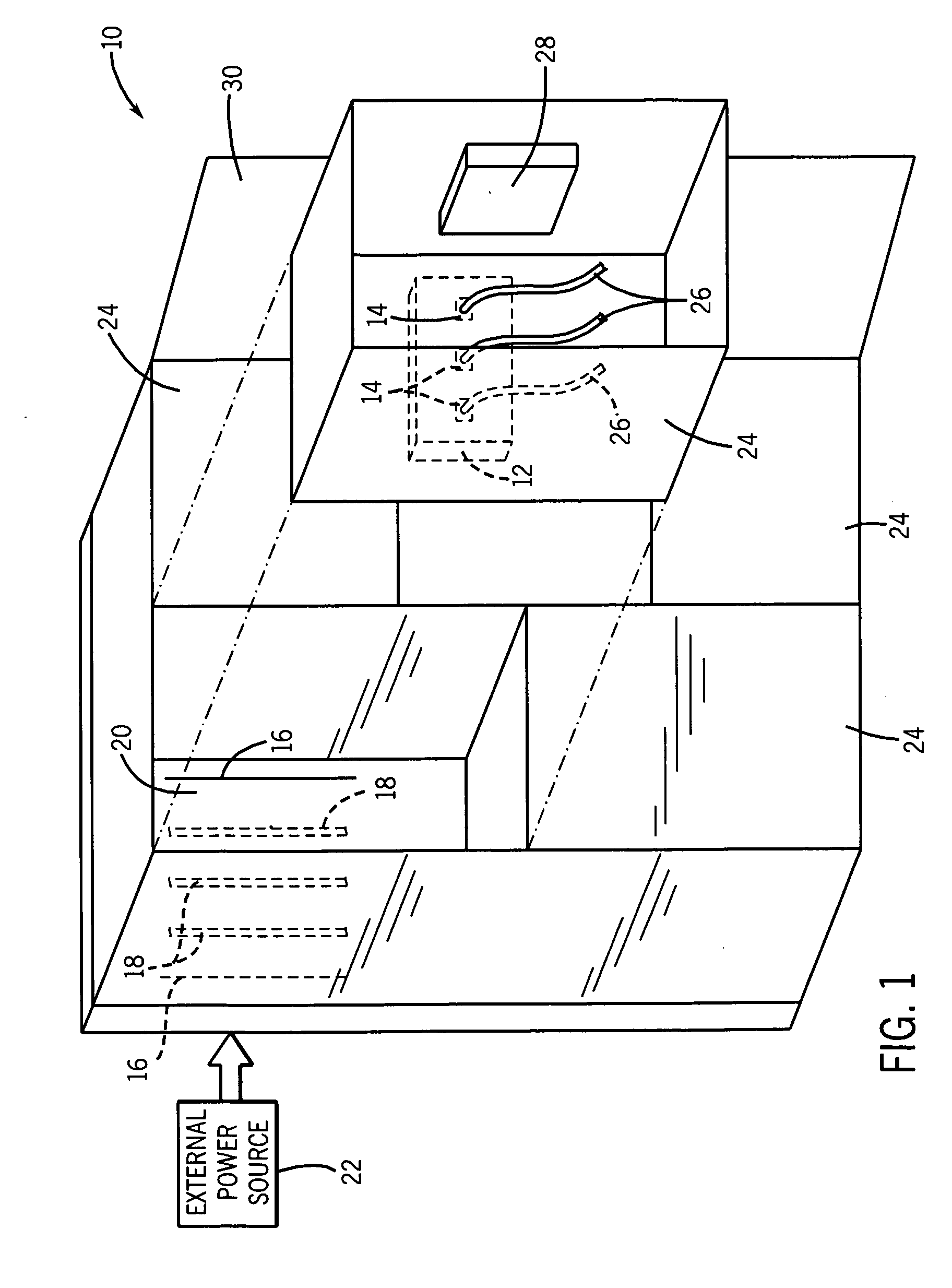
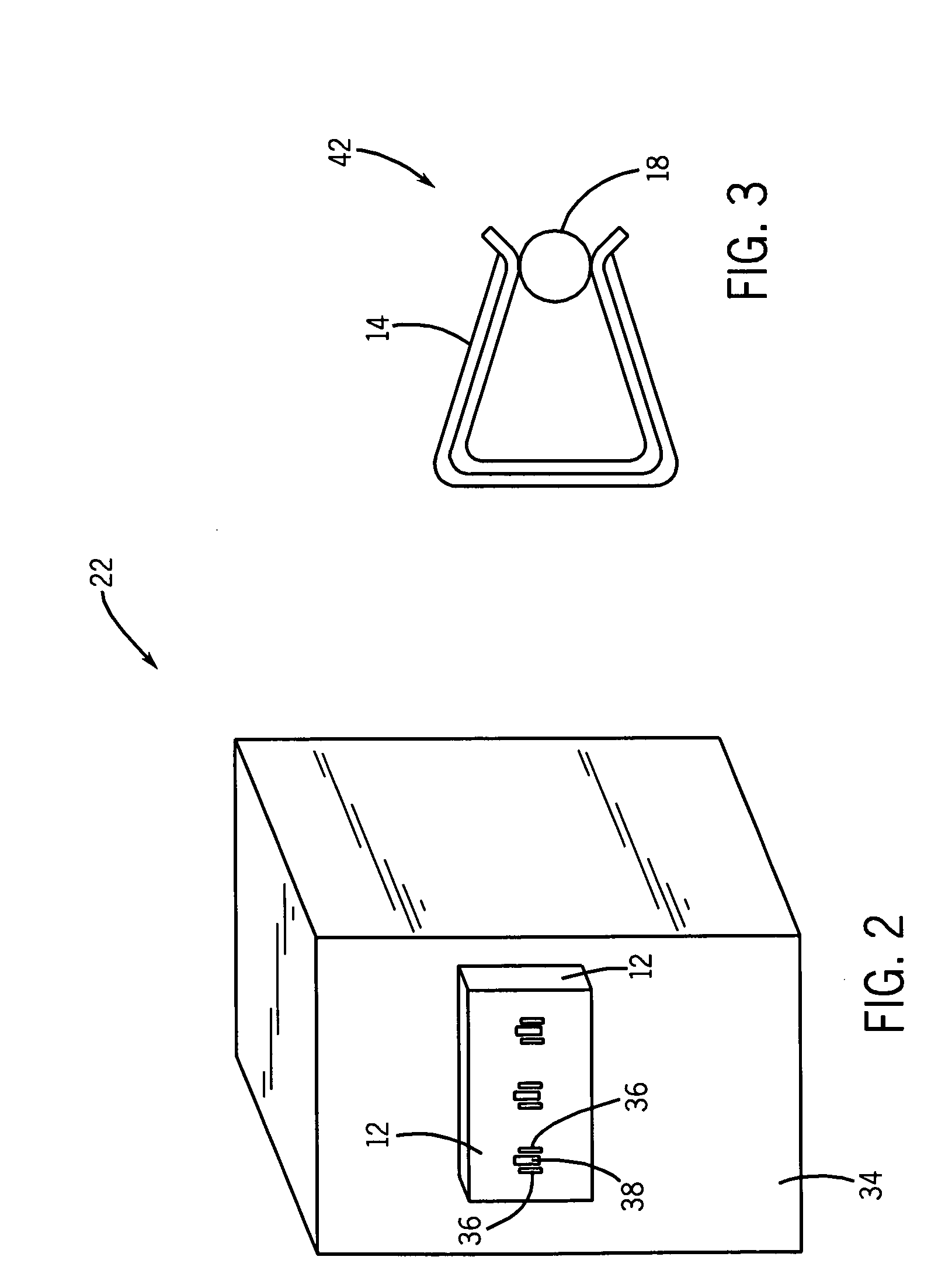
[0029] Beginning with FIG. 1, an exemplary motor control center (MCC) 10 formed of a large metal enclosure includes a stab housing 12 that isolates electrical connectors, such as metal power stabs 14. The stabs 14 are configured to engage the vertical power bus (bars) 18 through openings in a vertical bus cover 16 at the back wall 20 of the MCC 10. In this example, the vertical power bus 18 receives power from a horizontal power bus which in turn receives power, such as 208 to 690 volt ac power, from an external power source 22. Thus, in this embodiment, the three vertical power bus bars 18 deliver three phase ac power to the three stabs 14 at the bucket or unit 24. To form an electrical connection or termination, the stabs 14 engage the bars 18 as the unit 24 is slid into its respective cavity where the unit 24 resides during normal operation.

[0030] Power leads 26 electrically couple to the stabs 14 and deliver power to components 28, such components 28 including fuses, circuit br...


PUM


Abstract

The present technique, applicable to low voltage, medium voltage, and high voltage MCCs and other power management systems, provides for substantially containing and directing an arcing fault and resultant ionized gases within a stab enclosure or housing disposed in the MCC. For example, the stab housing may have reduced stab-openings at the power bus interface to diminish the potential of an arc flash (and ionized gases) from reaching the power buses. Furthermore, phase-to-phase isolation barriers may be employed within the stab housing to reduce the potential of an arcing fault going phase-to-phase. Moreover, to reduce arc flash damage within the MCC, the walls and barriers, including walls around the stabs, within the housing may be configured to direct the arc on a preferred path to a desired location within the housing to extinguish the arc in less than 0.1 second or 6 cycles, or even less than 0.033 second or 2 cycles.

Description

BACKGROUND [0001] The present technique relates generally to the field of power supply, such as that to motor control centers (MCCs). Specifically, the invention relates to techniques for connecting incoming power supply to certain types of electrical machinery, such as MCC's and components, for protecting such connections, and for containing and extinguishing arcing within such systems when faults do occur. [0002] Systems that distribute electrical power for residential, commercial, and industrial uses can be complex and widely divergent in design and operation. Electrical power generated at a power plant may be processed and distributed via substations, transformers, power lines, and so forth, prior to receipt by the end user. The user may receive the power over a wide range of voltages, depending on availability, intended use, and other factors. In large commercial and industrial operations, the power may be supplied as three phase ac power (e.g., 208 to 690 volt ac, and higher) ...

Claims


Application Information

Patent Timeline
IPC IPC(8): H02H3/00
CPCH02B11/04H01R25/142H01R13/18H01R4/184H02B1/36H02B13/025
Inventor MALKOWSKI, CHESTER JR.JAMALEDDIN, EMMAD A.RACINOWSKI, WAYNE
Owner ROCKWELL AUTOMATION TECH
Why Eureka
Try Eureka