Method and apparatus for measuring jitter

a technology of jitter measurement and apparatus, applied in the field of jitter measurement, can solve the problems of circuit failure to operate properly, device rejection or “binned” of the signal, and the unavoidable amount of jitter in every signal

Active Publication Date: 2006-03-30
TERADYNE
View PDF22 Cites 20 Cited by
  • Summary
  • Abstract
  • Description
  • Claims
  • Application Information

AI Technical Summary

Benefits of technology

[0015] In some embodiments, the method of characterizing jitter in a signal is used to verify the performance of a programmable jitter injection device.
[0016] In another aspect, the invention relates to a method of verifying the performance of a programmable jitter injection device. The method includes programming the jitter injection device to generate a jitter modulated signal having a programmed amount of jitter, the jitter modulated signal being modulated according to a modulating function; forming a histogram of times of occurrence of a value of the jitter modulated signal; fitting a probability distribution function to the histogram, the probability distribution function having a component proportion to a probability distribution function of the modulating function and a component proportional to a probability distribution function of a random function; and characterizing jitter from the component proportional to a probability distribution function of the modulating of the probability distribution function fit to the histogram.

Problems solved by technology

Jitter is a characteristic of periodic signals that is often undesirable.
Jitter might be introduced into a signal by many sources, including electrical interference that creates noise.
Approximations in representing signal values and other errors in a circuit might all contribute to jitter.
Some amount of jitter is unavoidable in every signal.
However, some circuits are designed assuming that the signals they process have a specific period or take on specific values at defined times. If there is too much jitter in these signals, the circuits might fail to operate properly.
Conversely, if it does not operate properly, the device might be rejected or “binned” as a part having a reduced jitter immunity specification.
However, these devices often have limited bandwidth or frequency responses that make them unsuitable for high frequency measurements.

Method used


Image

  • Method and apparatus for measuring jitter
  • Method and apparatus for measuring jitter
  • Method and apparatus for measuring jitter

Examples


Embodiment Construction

[0030] This invention is not limited in its application to the details of construction and the arrangement of components set forth in the following description or illustrated in the drawings. The invention is capable of other embodiments and of being practiced or of being carried out in various ways. Also, the phraseology and terminology used herein is for the purpose of description and should not be regarded as limiting. The use of “including,”“comprising,” or “having,”“containing,”“involving,” and variations thereof herein, is meant to encompass the items listed thereafter and equivalents thereof as well as additional items.

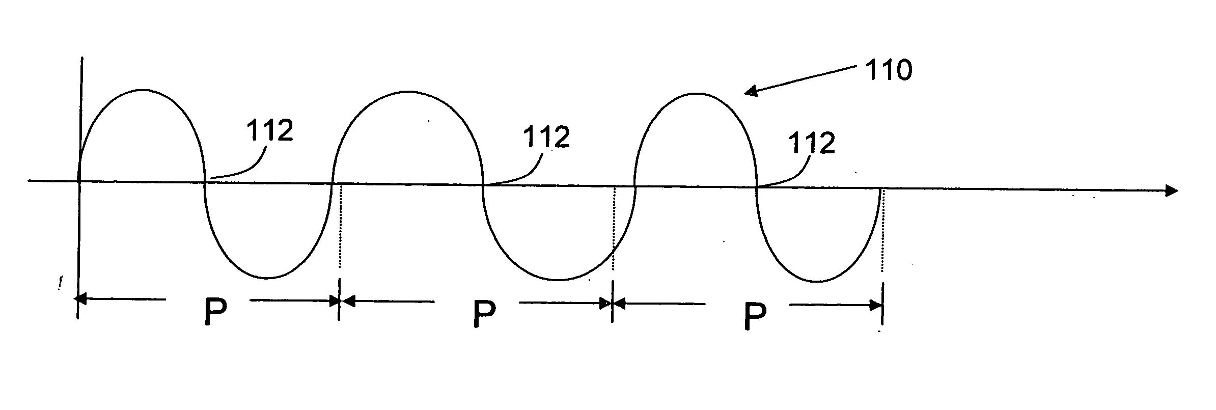
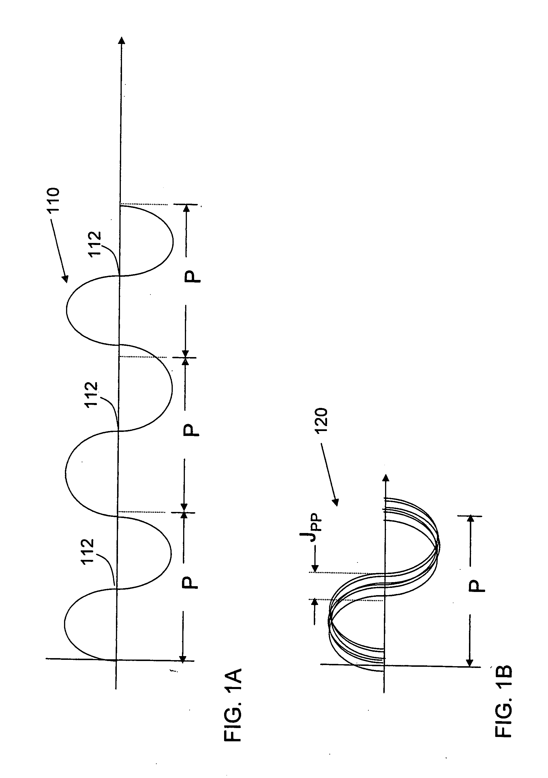
[0031]FIG. 1A is a sketch of a periodic signal 110. Signal 110 has a nominal period P, meaning that on average each cycle of the periodic signal 110 occurs in the time P. Signal 110 might, for example, be a sine wave. Signal 110 has a positive to negative zero crossing 112 that occurs once per cycle.

[0032]FIG. 1B illustrates a curve 120 formed by superimposin...


PUM


Abstract

A system and method for characterizing the jitter of a periodic signal. Samples of the signal are taken with a sampling device. A set of samples representing a particular value of the signal in multiple cycles of the periodic signal is collected. Those values are formed into a histogram. The histogram is matched to a probability distribution function. By identifying parameters that shape the probability distribution function to match the histogram of actual samples, characteristics of the jitter are determined. This technique may be employed as part of the calibration or verification of the jitter injection instrument such as might be used for testing semiconductor devices. Measurements may be made with a sampling device that is calibrated to NIST standards. In this way, the jitter measurements become NIST traceable.

Description

BACKGROUND OF INVENTION [0001] 1. Field of Invention [0002] This invention relates generally to electronic test and measurement equipment and more specifically to the measurement of jitter. [0003] 2. Discussion of Related Art [0004] Jitter is a characteristic of periodic signals that is often undesirable. If a signal is perfectly periodic, it will repeatedly take on the same value at points in time that are spaced by exactly the period of the signal. Jitter is the differences between the actual time at which the value recurs and the nominal times at which it should recur in a perfectly periodic signal. [0005] Jitter might be introduced into a signal by many sources, including electrical interference that creates noise. Approximations in representing signal values and other errors in a circuit might all contribute to jitter. [0006] Some amount of jitter is unavoidable in every signal. If the jitter is a relatively small fraction of the period of the signal, it is unlikely to impact t...

Claims


Application Information

Patent Timeline
Patent Type & Authority Applications(United States)
IPC IPC(8): H04B17/00
CPCG01R29/26H04L1/20G01R31/31709
Inventor TEK, MEHMET NEJATLIU, CHIBING
Owner TERADYNE
Why Eureka
Try Eureka