Film forming method and film forming apparatus

a film forming and ad method technology, applied in the field of film forming methods and film forming apparatuses, can solve the problems of shortening affecting the selection of the material, and the complexity of the forming of the film pattern is further required, so as to achieve the effect of raising the property value of the ad film

Inactive Publication Date: 2006-03-30
FUJIFILM CORP +1
View PDF5 Cites 21 Cited by
  • Summary
  • Abstract
  • Description
  • Claims
  • Application Information

AI Technical Summary

Benefits of technology

[0014] According to the present invention, since the crystal orientation of the raw material powder is controlled by applying a magnetic field to the raw material powder in an aerosol state, the crystal orientation in the AD film deposited on the substrate can be orientated in a desired orientation. Therefore, the property values of the AD film can be raised.

Problems solved by technology

However, according to JP-P2003-342100A or JP-P2004-131363A, since bulk material formation or film formation under high temperature environment or wet condition is mainstream, the steps are large in number, complicated, and troublesome.
Further, when the fabricated functional material is applied to a device, a complicated step of forming a film pattern is further required.
However, there is a problem that a film formed by the AD method (hereinafter, also referred to as “AD film”) falls short of property values such as piezoelectric performance of a bulk material having the same composition.

Method used


Image

  • Film forming method and film forming apparatus
  • Film forming method and film forming apparatus
  • Film forming method and film forming apparatus

Examples


first embodiment

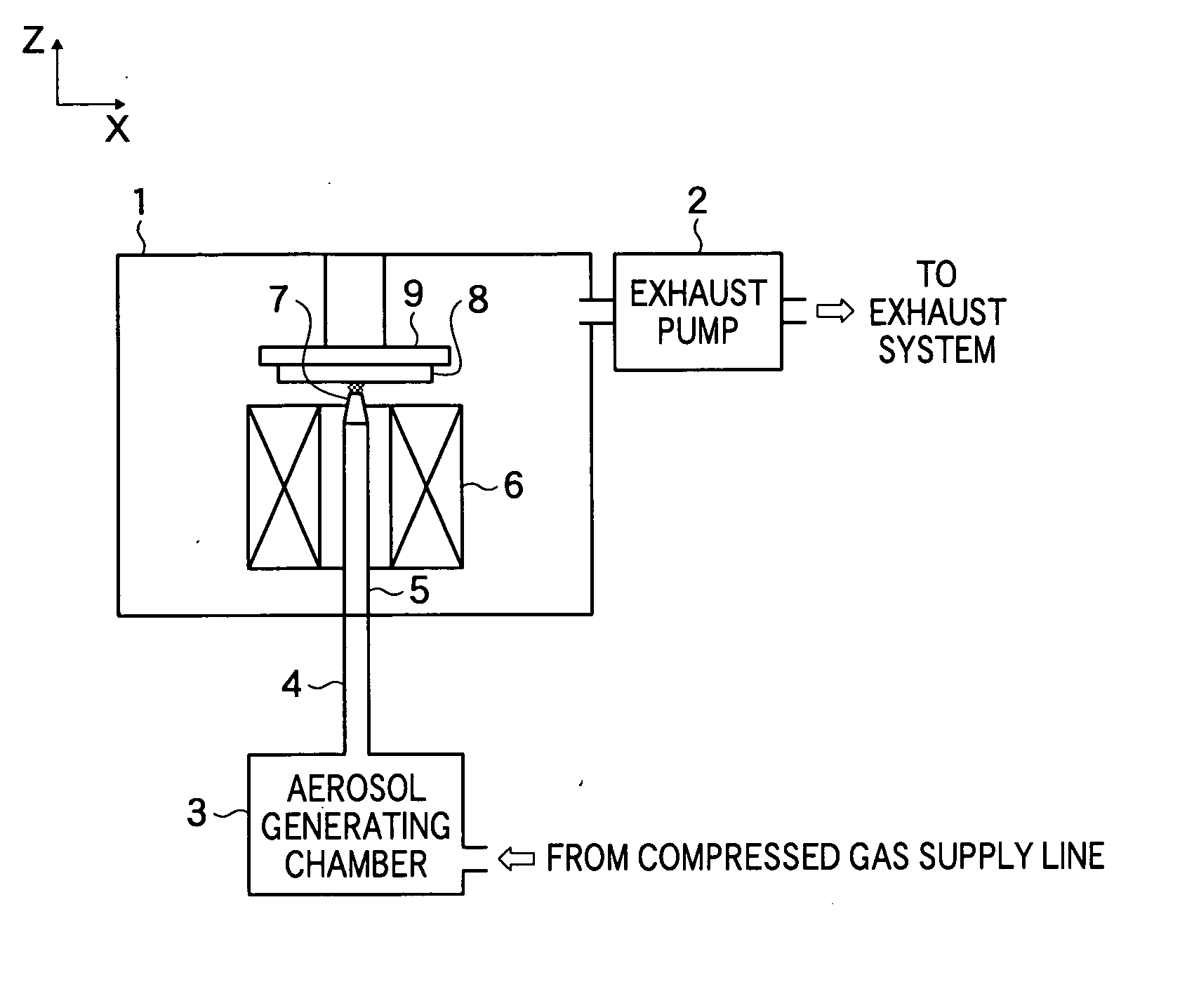
[0026]FIG. 1 is a schematic diagram showing a film forming apparatus according to the present invention. This film forming apparatus uses the aerosol deposition (AD) method of spraying and depositing a raw material powder (film formation material powder) on a lower layer, and includes a chamber 1 in which film formation is performed, an exhaust pump 2, an aerosol generating chamber 3, an aerosol transport line 4, an accelerating tube 5, a superconducting coil 6, an injection nozzle 7, and a substrate stage 9 for holding a substrate 8. Among those, the superconducting coil 6 is part of a superconducting magnet as a magnetic field application device provided in the film forming apparatus, and a cooling unit as another component element of the superconducting magnet, a power supply unit for supplying current to the coil, etc. are omitted in FIG. 1.

[0027] The exhaust pump 2 maintains the pressure within the chamber 1 at predetermined pressure by exhausting air within the chamber 1.

[002...

second embodiment

[0045] Next, a film forming apparatus according to the present invention will be described by referring to FIGS. 9 to 10B. FIG. 9 is a schematic diagram showing a constitution of the film forming apparatus according to the embodiment.

[0046] The film forming apparatus shown in FIG. 9 has electrodes 50a and 50b and a power supply unit 51 in addition to the film forming apparatus shown in FIG. 1. The electrode 50a and the electrode 50b are oppositely located with the flow path of the aerosol injected from the injection nozzle 7 in between. The power supply unit 51 provides a potential difference between the electrode 50a and the electrode 50b so as to form an electric field in a predetermined direction (Y-direction in FIG. 9) in a region including the flow path of the aerosol. Other constitution is the same as that of the film forming apparatus shown in FIG. 1.

[0047]FIGS. 10A and 10B are diagrams for explanation of the principle of a film forming method to be used in the film forming ...


PUM

PropertyMeasurementUnit
particle diameteraaaaaaaaaa
absolute temperatureaaaaaaaaaa
magnetic fieldaaaaaaaaaa

Abstract

A film forming apparatus by which property values in a film formed by the AD method can be improved. The film forming apparatus includes: a chamber having a substrate stage for holding a substrate on which a film is to be formed; an aerosol generating unit for generating an aerosol by dispersing a raw material powder into a gas; a magnetic field applying device for applying a magnetic field to a flow path of the aerosol generated by the aerosol generating unit so as to orient crystal orientation in the raw material powder in an aerosol state; and an injection nozzle for spraying the aerosol applied with the magnetic field by the magnetic field applying device to the substrate so as to deposit the raw material powder, in which the crystal orientation is oriented, on the substrate.

Description

BACKGROUND OF THE INVENTION [0001] 1. Field of the Invention [0002] The present invention relates to a film forming method and a film forming apparatus, and specifically, to a film forming method and a film forming apparatus for spraying and depositing a raw material powder on a substrate or the like. [0003] 2. Description of a Related Art [0004] Recent years, a technique of controlling crystal orientation in a solid material such as metal or ceramics in order to control and improve characteristics of the material has been attracting attention. For example, a functional material having an advantageous electric characteristic in a specific direction and a high-strength material strong in bending stress in a specific direction can be fabricated by orienting crystal grains. As a technique of fabricating such a functional material, an orientation control technique of performing treatment such as crystal growth, sol-gel deposition, HIP (hot isostatic pressing), or SIP (non-pressure sinte...

Claims


Application Information

Patent Timeline
Patent Type & Authority Applications(United States)
IPC IPC(8): C23C16/00B05D1/02H01F41/00B01J19/08B05B5/025C23C24/08H01L41/18H01L41/314H01L41/39
CPCB05D1/12H01F41/20C30B30/04C23C24/04
Inventor OSAWA, ATSUSHI
Owner FUJIFILM CORP
Why Eureka
Try Eureka