Welding tape and related taping method

a welding tape and related technology, applied in the field of welding tape, can solve the problems of inferior welding, unwanted contaminant formation on the inside of the pipe, and the adhesion tends to remain on the pipe, and achieve the effect of facilitating tape alignmen

Inactive Publication Date: 2006-03-30
HACIKYAN MICHAEL
View PDF1 Cites 18 Cited by
  • Summary
  • Abstract
  • Description
  • Claims
  • Application Information

AI Technical Summary

Benefits of technology

[0012] In exemplary embodiments of the invention, the welding tape's adhesive pattern is configured such that the adhesive-free zone is longitudinally centered between a pair of laterally disposed adhesive regions. In an exemplary installation method, one adhesive region is adhered to one structure to be welded, such as a first pipe, and the other adhesive region is adhered to the other structure to be welded, such as a second pipe. The welding tape will be positioned so that the adhesive-free zone is substantially centered over the junction between the structures. A visual indication may be provided on the non-adhesive side of the welding tape to facilitate tape alignment.

Problems solved by technology

One of the problems associated with use of conventional welding tape is that some of the adhesive tends to remain on the pipe as the tape is peeled back.
This adhesive residue can cause fouling when it is heated during welding, resulting in an inferior weld and / or unwanted contaminant formation on the inside of the pipe.

Method used


Image

  • Welding tape and related taping method
  • Welding tape and related taping method
  • Welding tape and related taping method

Examples


Embodiment Construction

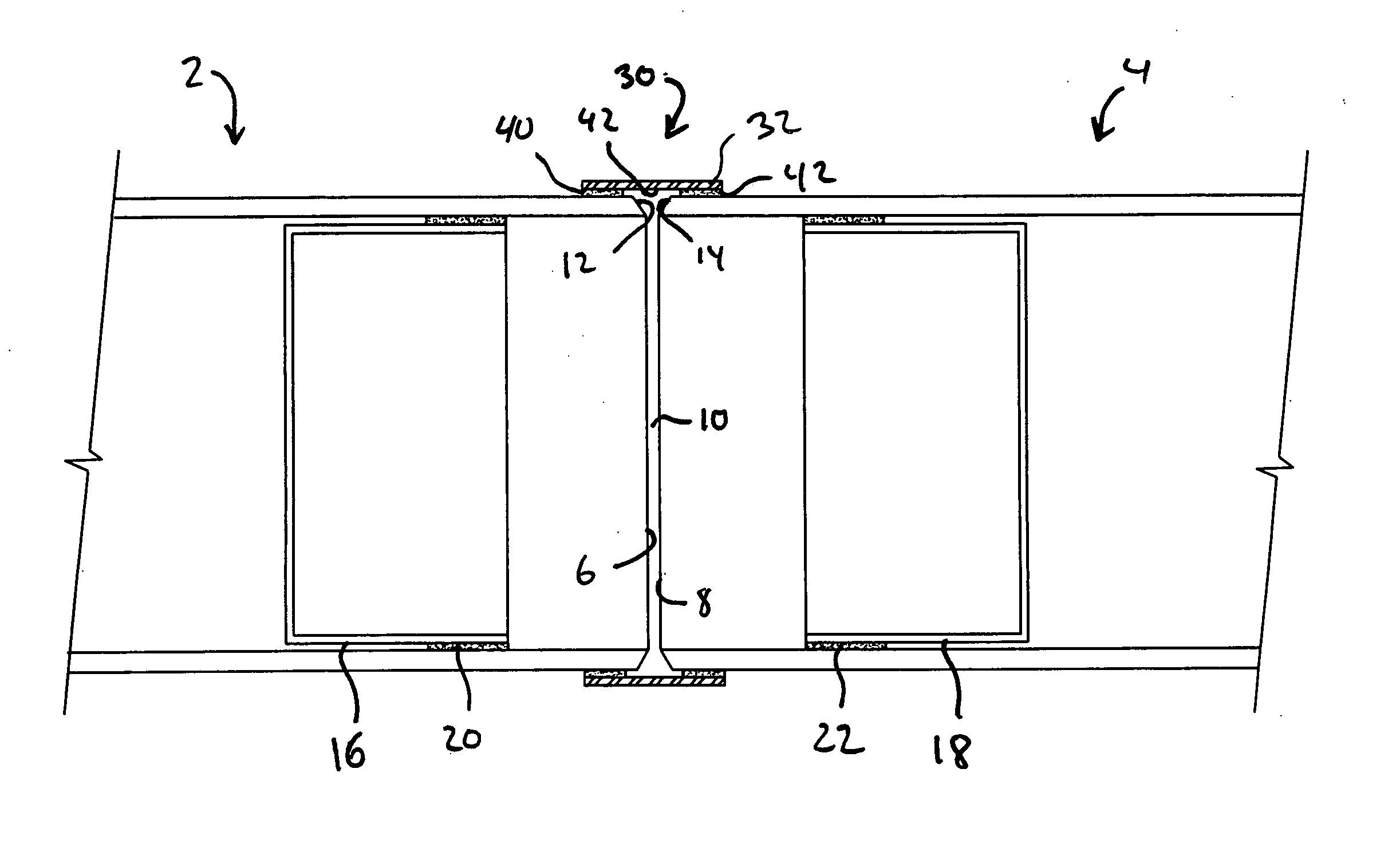
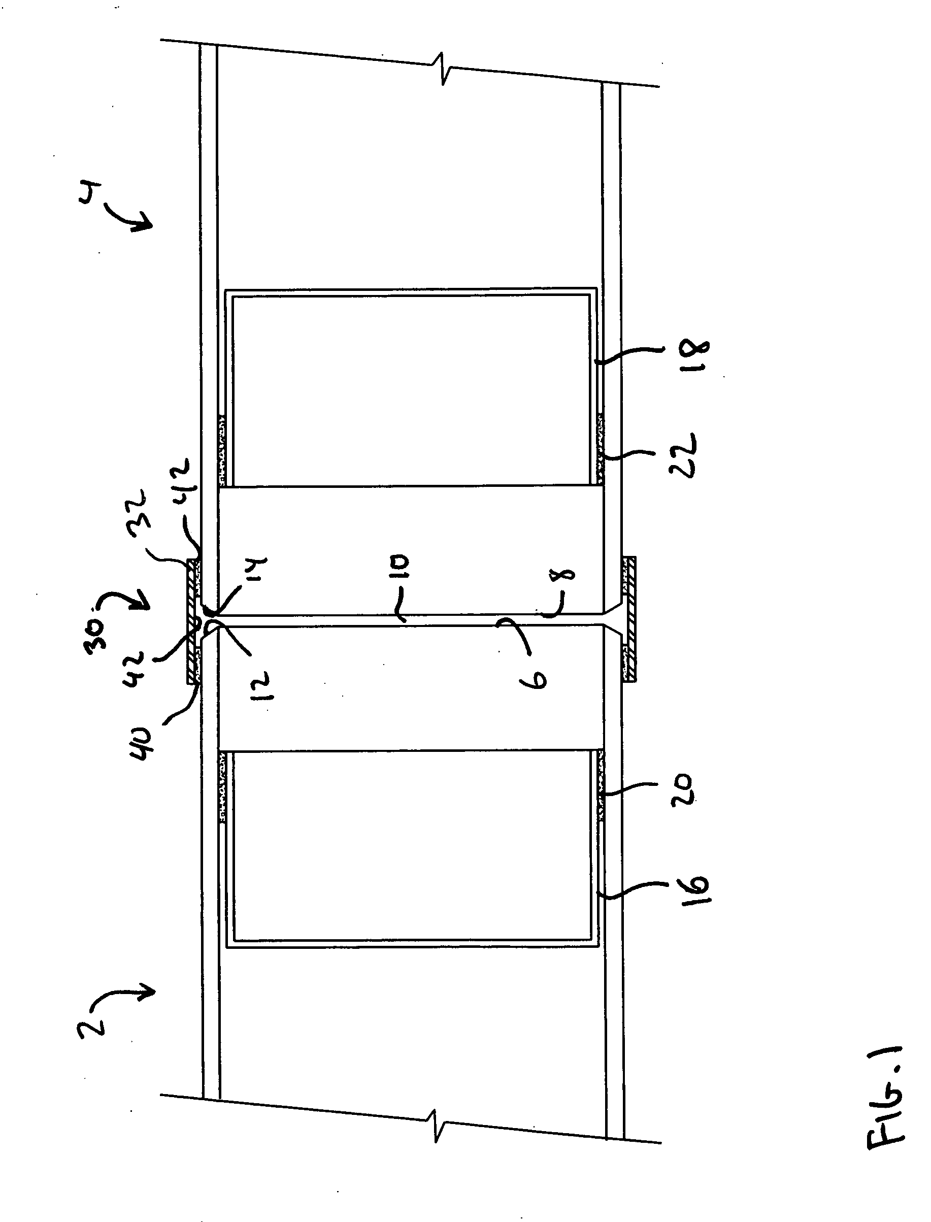
[0021] Turning now to the Drawings, which are not necessarily to scale, FIG. 1 illustrates a pair of pipes 2 and 4 that are situated so that the respective ends 6 and 8 thereof are adjacently disposed in closely spaced relationship. This placement defines a circumferential pipe junction 10 where a pipe joint is to be welded. The ends 6 and 8 of the pipes 2 and4 are respectively chamfered at 12 and 14 in order to facilitate the formation of a conventional butt weld. It will be appreciated that the pipe ends 6 and 8 could also be non-chamfered. As indicated by way of background above, the junction 10 is formed with a small gap so that an inert gas can be introduced into the interior region of the pipes 2 and 4 using a conventional purge gas needle injector. As additionally discussed by way of background above, alternative purge gas introduction means could be used, such that a gap between the pipe ends 6 and 8 would not be required, and the pipe ends could be substantially abutting. N...


PUM

PropertyMeasurementUnit
sizeaaaaaaaaaa
areaaaaaaaaaaa
lengthaaaaaaaaaa

Abstract

An inert gas welding tape for retaining a purge gas around a weld zone that is situated at a junction between two structures to be welded together by inert gas welding. The welding tape includes a flexible substrate and a pattern of adhesive on one side of the substrate. The adhesive pattern defines an adhesive-free zone that is substantially free of adhesive and spans the weld zone when the tape is mounted on the structures to be welded, such that substantially no adhesive will be present in the weld zone. The adhesive regions of the adhesive pattern will only contact the structures in areas that are outside of the weld zone. At installation time, a length of the welding tape is selected and any adhesive backing thereon is removed. The welding tape is then positioned over the structures to be welded, preferably with the adhesive-free zone substantially centered over the junction that forms part of the weld zone. With the welding tape in this position, the adhesive regions of the welding tape are adhered to areas of each structure that are outside of the weld zone.

Description

BACKGROUND OF THE INVENTION [0001] 1. Field of the Invention [0002] The present invention relates generally to inert gas welding. More particularly, the invention is directed to welding tape for retaining purge gas around a weld zone. [0003] 2. Description of Prior Art [0004] By way of background, inert gas welding is a species of arc welding in which the molten weld pool is shielded from atmospheric contamination and oxidation by bathing it with an inert gas, such as Argon, or a mixture of Helium and Argon. Popular examples of inert gas welding include TIG (Tungsten Inert Gas) welding and MIG (Metal Inert Gas) welding. [0005] When welding together pipes and other enclosed structures using inert gas welding, it is important to purge the interior of the pipe or structure in the vicinity of the weld zone to prevent corrosion and the formation of oxides on the interior side of the weld pool. Sealing devices such as purge dams, bladders, and other barriers are conventionally used for th...

Claims


Application Information

Patent Timeline
Patent Type & Authority Applications(United States)
IPC IPC(8): B32B33/00
CPCB23K9/326C09J7/20C09J2301/204Y10T428/14Y10T428/24752Y10T428/24802
Inventor HACIKYAN, MICHAEL
Owner HACIKYAN MICHAEL
Why Eureka
Try Eureka