Flow-through chemical and biological sensor

a flow-through chemical and biological sensor technology, applied in the field of optical sensors, can solve the problems of low detection efficiency, limited detection limit, and difficulty in detection of small amounts of analyte in a large volume of sample, and achieve the effect of higher index of refraction material

Inactive Publication Date: 2006-03-30
CREATV MICROTECH
View PDF18 Cites 58 Cited by
  • Summary
  • Abstract
  • Description
  • Claims
  • Application Information

AI Technical Summary

Benefits of technology

[0013] The invention provides a mixing flow apparatus. The mixing flow apparatus consists of a waveguide and a mixing flow chamber; the waveguide having a higher index of refraction material than its surroundings for propagation of a signal, and the mixing flow chamber having a body forming a flow chamber with an inlet, an outlet, a radiation transmissive wall and a surface positioned to disrupt flow regularity of a sample fluid, the body of the mixing flow chamber surrounding at least a portion of the waveguide, wherein constituents of a sample fluid entering the inlet are mixed by disruption of sample fluid flow regularity prior to discharge at the outlet. Also provided is a detection apparatus. The detection apparatus consists of a waveguid

Problems solved by technology

Even with all the available detection methods, the detection of low concentrations of analyte, i.e., a small amount of analyte in a large volume of sample, is still a challenge.
Some immunoassays can only process a few micro-liters of the whole sample.
Howe

Method used


Image

  • Flow-through chemical and biological sensor
  • Flow-through chemical and biological sensor
  • Flow-through chemical and biological sensor

Examples


Embodiment Construction

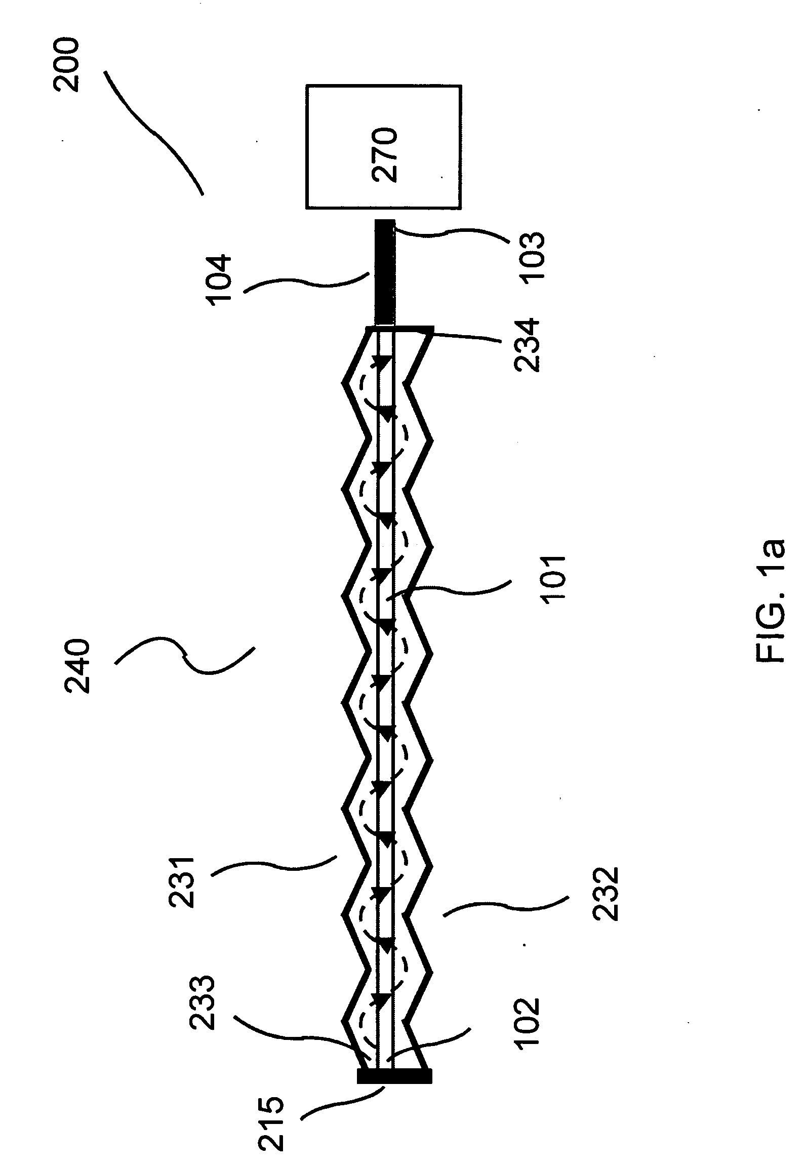
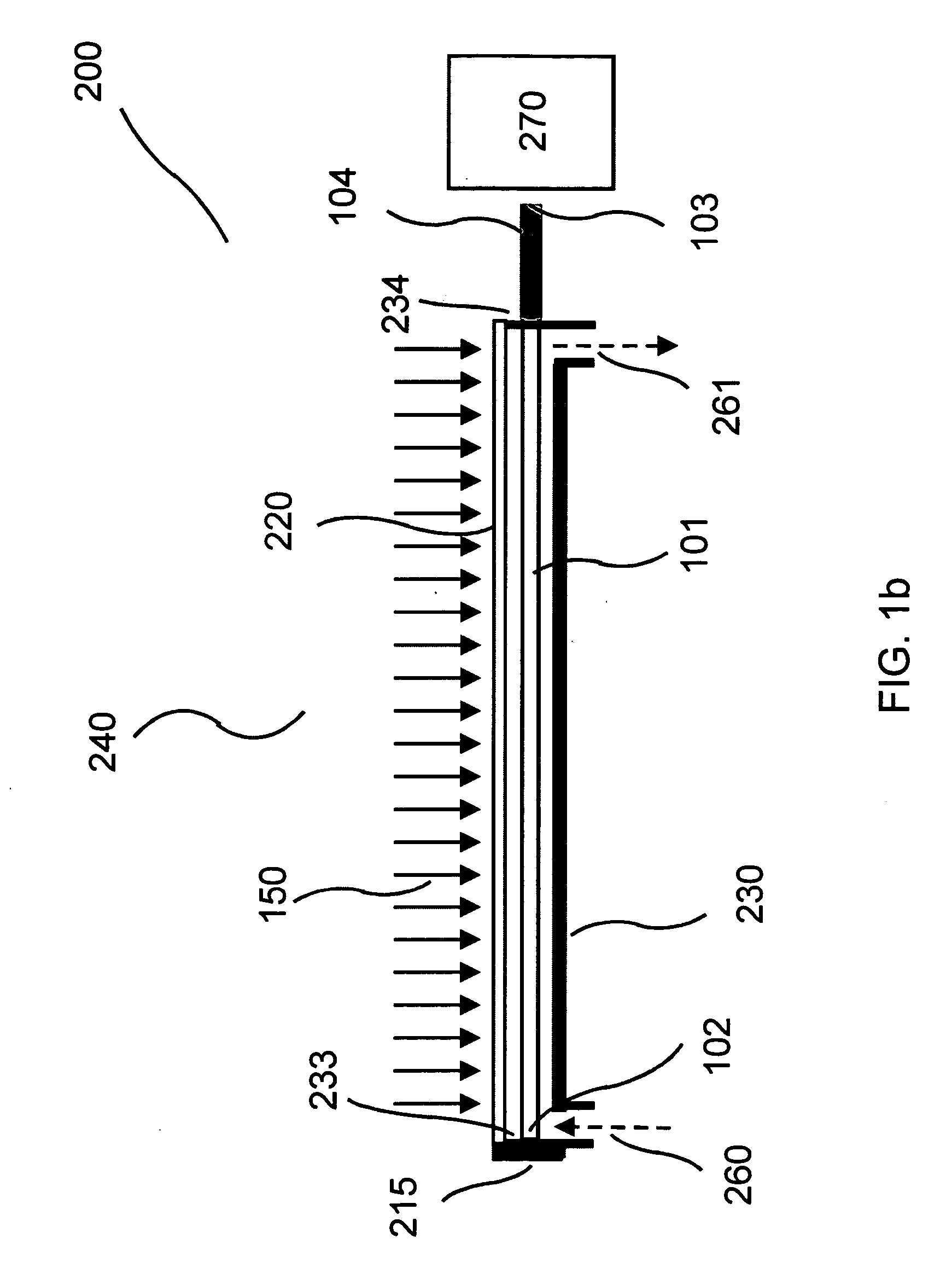
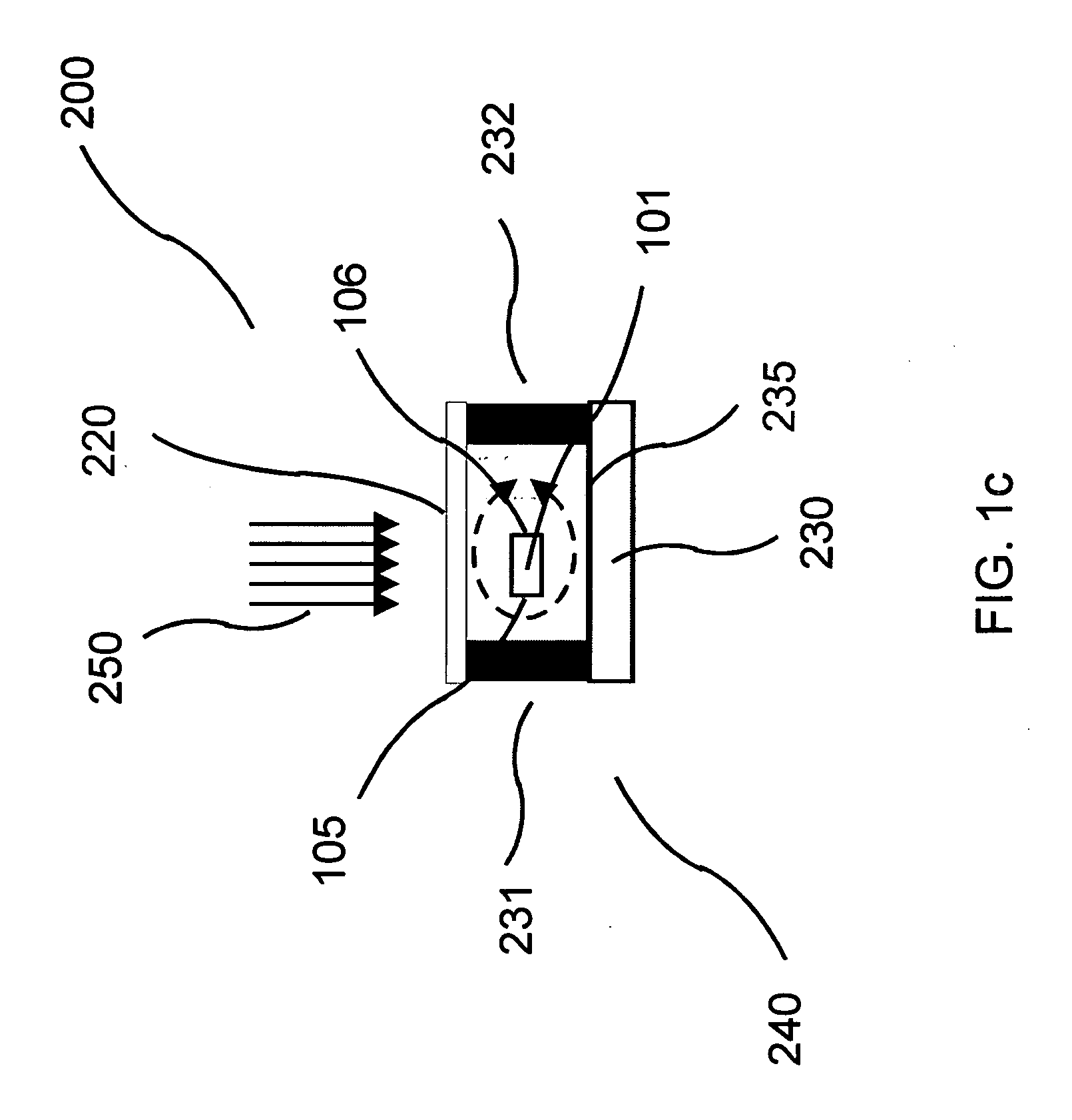
[0036] The invention provides a flow-through optical sensor wherein the interactions between the constitutive elements of the fluid and the waveguide surface are enhanced in order to maximize the capture of the analyte to the surface of the optical waveguide. Also provided is a sensor having at least one waveguide for each flow channel. Sensors of the invention are provided that allow for the detection of at least one analyte on each waveguide. Further, the invention also provides multiple channels and each channel with at least one waveguide as well as multiple waveguides in each channel. Illumination of the optical sensor and waveguide therein such as by excitation using radiation that is collimated or non-collimated, is also provided. The illumination of the waveguide can be coherent or incoherent. The illumination source can be a point source or a diffused source. Also provided is illumination of the optical sensor and waveguide therein such as by excitation using radiation that...


PUM


Abstract

The invention provides a mixing flow apparatus. The mixing flow apparatus consists of a waveguide and a mixing flow chamber; the waveguide having a higher index of refraction material than its surroundings for propagation of a signal, and the mixing flow chamber having a body forming a flow chamber with an inlet, an outlet, a radiation transmissive wall and a surface positioned to disrupt flow regularity of a sample fluid, the body of the mixing flow chamber surrounding at least a portion of the waveguide, wherein constituents of a sample fluid entering the inlet are mixed by disruption of sample fluid flow regularity prior to discharge at the outlet. Also provided is a detection apparatus. The detection apparatus consists of a waveguide, a mixing flow chamber and a radiation detector; the waveguide having a higher index of refraction material than its surroundings for propagation of a signal; the mixing flow chamber having a body forming a flow chamber with an inlet, an outlet, a radiation transmissive wall and a surface positioned to disrupt flow regularity of a sample fluid, the body of the mixing flow chamber surrounding at least a portion of the waveguide, wherein constituents of a sample fluid entering the inlet are mixed by disruption of sample fluid flow regularity prior to discharge at the outlet, and the radiation detector being disposed facing the direction of oncoming propagated signal from the waveguide. The detection apparatus can include an illumination source.

Description

[0001] This application is based on, and claims the benefit of, U.S. Provisional Application No. 60 / 550,442, filed Mar. 5, 2004, entitled “Flow-Through Chemical and Biological Sensor,” the entire disclosure of which is incorporated herein by reference.[0002] This invention was made with government support under grant numbers R43 CA094430, R43 AI052684 and R43 EB001731 awarded by the National Institutes of Health. The United States Government has certain rights in this invention.BACKGROUND OF THE INVENTION [0003] The invention relates generally to optical sensors and, more particularly to waveguide flow-through sensors using a chemical or molecular recognition species to detect or capture the analytes, such as bacteria, viruses, spores, oocysts, cells, cell fragments, proteins, receptor and binding proteins, nucleic acid (DNA, cDNA, RNA), oligonucleotides, antibodies, enzymes, antibiotics, peptides, carbohydrates, tumor and disease markers, toxins, organic and inorganic compounds and...

Claims


Application Information

Patent Timeline
IPC IPC(8): C12M1/34B01F5/06B01F13/00G01N21/05
CPCB01F5/0603G01N2021/0346B01F5/0647B01F13/0059B01L3/502715B01L2300/0654B01L2300/0861B01L2300/0867B01L2300/0877B01L2400/086B82Y15/00B82Y30/00G01N21/05G01N33/54373B01F5/0646B01F25/421B01F25/4331B01F25/433B01F33/30
Inventor TANG, CHA-MEIAMSTUTZ, PLATTE T. III
Owner CREATV MICROTECH
Why Eureka
Try Eureka