Stress-relief layers and stress-compensation collars with low-temperature solders for board-level joints, and processes of making same

a stress-relief layer and stress-compensation collar technology, applied in the direction of stress/warp reduction, sustainable manufacturing/processing, printed circuits, etc., can solve the problems of premature solder joint failure, thermal expansion-mismatch challenges, and reduced stress resistance of stress-relief layers and stress-compensation collars

Inactive Publication Date: 2006-03-30
INTEL CORP
View PDF2 Cites 12 Cited by
  • Summary
  • Abstract
  • Description
  • Claims
  • Application Information

AI Technical Summary

Problems solved by technology
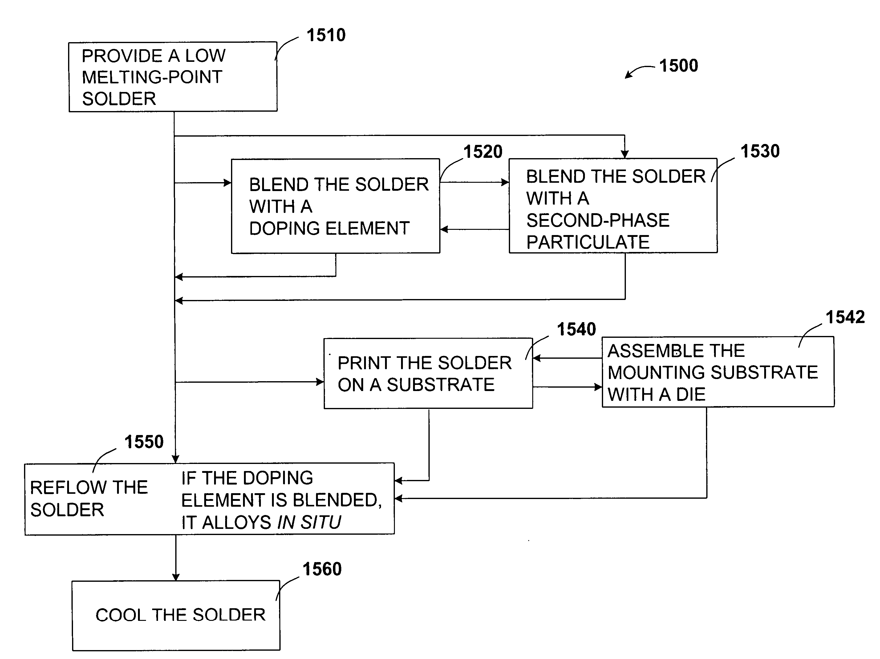
Thermal expansion-mismatch challenges exist between the die, the underfill material, and the substrate to which the die is mounted, and to connecting structures such as the motherboard.
One challenge with chip packaging technology is premature solder joint failure due to thermal stress.
With miniaturization of pitch, smaller ball size poses an increasing challenge to solder joint performance.
Two types of failure have been observed in solder bumps.
One type is fatigue due to thermal stressing at the solder joint.
Another type of failure results from mishandling the packages during processing, assembly, and transportation.
These failures are primarily due to higher stress levels at the solder bump-contact pad interface.
The solder joint has been observed to crack at the edges, and due to poor adhesion of the bumps to the pad, the solder has been observed to break away from the pad.

Method used


Image

  • Stress-relief layers and stress-compensation collars with low-temperature solders for board-level joints, and processes of making same
  • Stress-relief layers and stress-compensation collars with low-temperature solders for board-level joints, and processes of making same
  • Stress-relief layers and stress-compensation collars with low-temperature solders for board-level joints, and processes of making same

Examples


Embodiment Construction

[0030] The following description includes terms, such as upper, lower, first, second, etc., that are used for descriptive purposes only and are not to be construed as limiting. The embodiments of a device or article described herein can be manufactured, used, or shipped in a number of positions and orientations. The terms “die” and “processor” generally refer to the physical object that is the basic workpiece that is transformed by various process operations into the desired integrated circuit device. A die is usually singulated from a wafer, and wafers may be made of semiconducting, non-semiconducting, or combinations of semiconducting and non-semiconducting materials.

[0031] A board is typically a resin-impregnated fiberglass structure that acts as a mounting substrate for the die. A board can be prepared with a bond pad, also referred to as a bond finger, that is flush with the board, or the bond pad can be set upon the board surface. As depicted in this disclosure, a bond pad is...


PUM

PropertyMeasurementUnit
sizeaaaaaaaaaa
particle sizeaaaaaaaaaa
temperatureaaaaaaaaaa

Abstract

A stress-relief layer is formed by dispensing a polymer upon a substrate lower surface under conditions to partially embed a low melting-point solder bump that is disposed upon the lower surface. The stress-relief layer flows against the low melting-point solder bump. A stress-compensation collar is formed on a board to which the substrate is mated, and the stress-compensation collar partially embeds the low melting-point solder bump. An article that exhibits a stress-relief layer and a stress-compensation collar is also included. A computing system that includes the low melting-point solder, the stress-relief layer, and the stress-compensation collar is also included.

Description

TECHNICAL FIELD [0001] Disclosed embodiments relate to a stress-relief layer and a stress-compensation collar that surround a low melting-point solder in a microelectronic device package. BACKGROUND INFORMATION [0002] Chip packaging is often intensely involved with heat removal. Thermal expansion-mismatch challenges exist between the die, the underfill material, and the substrate to which the die is mounted, and to connecting structures such as the motherboard. The thermal mismatch often is exhibited at the joint of a solder bump and its bond pad. [0003] One challenge with chip packaging technology is premature solder joint failure due to thermal stress. Future packaging technology especially in the chipset application, will drive finer pitch as package size shrinks. With miniaturization of pitch, smaller ball size poses an increasing challenge to solder joint performance. [0004] Two types of failure have been observed in solder bumps. One type is fatigue due to thermal stressing at...

Claims


Application Information

Patent Timeline
Patent Type & Authority Applications(United States)
IPC IPC(8): H01L21/44
CPCH01L23/562H01L2924/01012H01L2224/16H01L2924/01025H01L2924/01046H01L2924/01057H01L2924/01077H01L2924/01078H01L2924/01079H01L2924/14H01L2924/1433H01L2924/15311H05K1/0271H05K3/3436H05K3/3463H05K2201/10977H05K2203/0126H01L2924/01327H01L24/16H01L2224/0554H01L2224/05568H01L2224/05573H01L2224/056H01L2224/16237H01L2924/00014Y02P70/50H01L2224/05599H01L2224/0555H01L2224/0556
Inventor SUH, DAEWOONGJAYARAMAN, SAIKUMARLEHMAN, STEPHEN E. JR.PATEL, MITESHBYRNE, TIFFANY A.MARTIN, EDWARD L.BASIRON, MOHD ERWAN B.LOH, WEI KEATLIM, SHEAU HOOICHIN, YOONG TATT P.
Owner INTEL CORP
Why Eureka
Try Eureka