
Method and system for testing memory using hash algorithm

a technology of memory and hash algorithm, applied in the field of methods and systems for testing memory using hash algorithm, can solve the problems of high cost of test equipment and test time, and achieve the effect of reducing test time, cost and complexity of external test system

Inactive Publication Date: 2006-03-30
LIU YEN FU
View PDF3 Cites 15 Cited by
  • Summary
  • Abstract
  • Description
  • Claims
  • Application Information

AI Technical Summary

Benefits of technology

[0005] It is therefore an objective of the present invention to provide a method for testing a memory, where the method can significantly reduce the test time, the cost, and the complexity of external test system.
[0007] It is still another objective of the present invention to provide a method for testing a memory, where the method generates a set of pseudo-random data pattern and the inverted value of the same set of pseudo-random data pattern to effectively detect “stuck-at” (logic-1 or logic-0) faults.
[0008] It is still another objective of the present invention to provide a method for testing a memory, where the method uses a hash algorithm to generate a signature representing the response data so that the test complexity is significantly reduced.
[0009] It is still another objective of the present invention to provide a test system for testing a memory, where the test system can be easily integrated into a chip containing the memory.
[0012] The invention has at least the following advantages. The method described in the invention can significantly reduce the test time, the cost, and the complexity of external test system. The method can provide both Automatic Test Pattern Generation (ATPG) and Accelerated Test Method (ATM) verification solutions. The method generates a set of pseudo-random data pattern and the inverted value of the same set of pseudo-random data pattern to effectively detect “stuck-at” (logic-1 or logic-0) faults. The method uses a hash algorithm to generate a signature representing the response data so that the test complexity is significantly reduced. The test system described in the invention can be easily integrated into a chip containing the memory.

Problems solved by technology

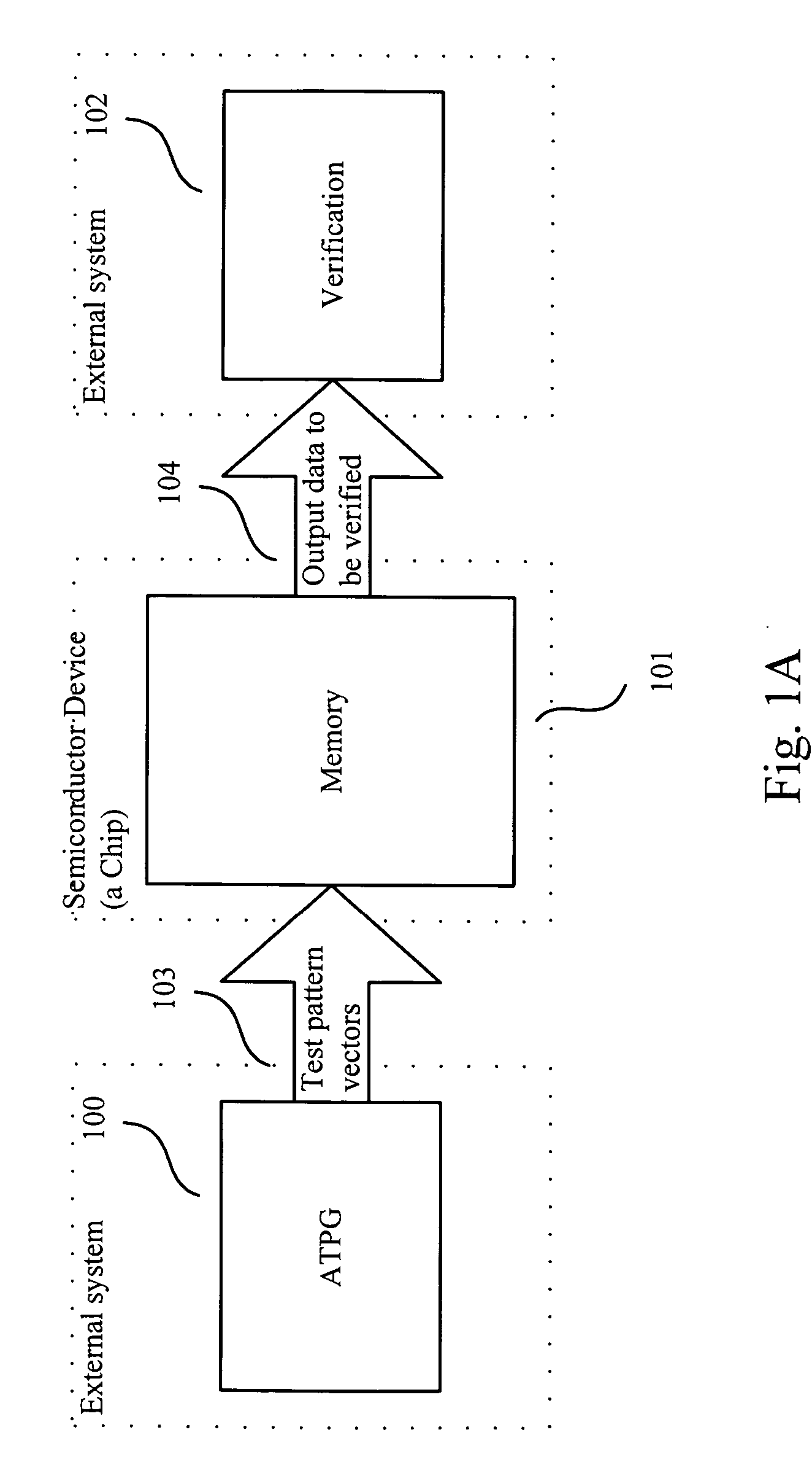
Though this methodology has been a de-facto standard of memory testing, the cost remained high for the test equipment and the test time.

Method used


Image

  • Method and system for testing memory using hash algorithm
  • Method and system for testing memory using hash algorithm
  • Method and system for testing memory using hash algorithm

Examples


Embodiment Construction

[0028] Reference will now be made in detail to the present preferred embodiments of the invention, examples of which are illustrated in the accompanying drawings. Wherever possible, the same reference numbers are used in the drawings and the description to refer to the same or like parts.

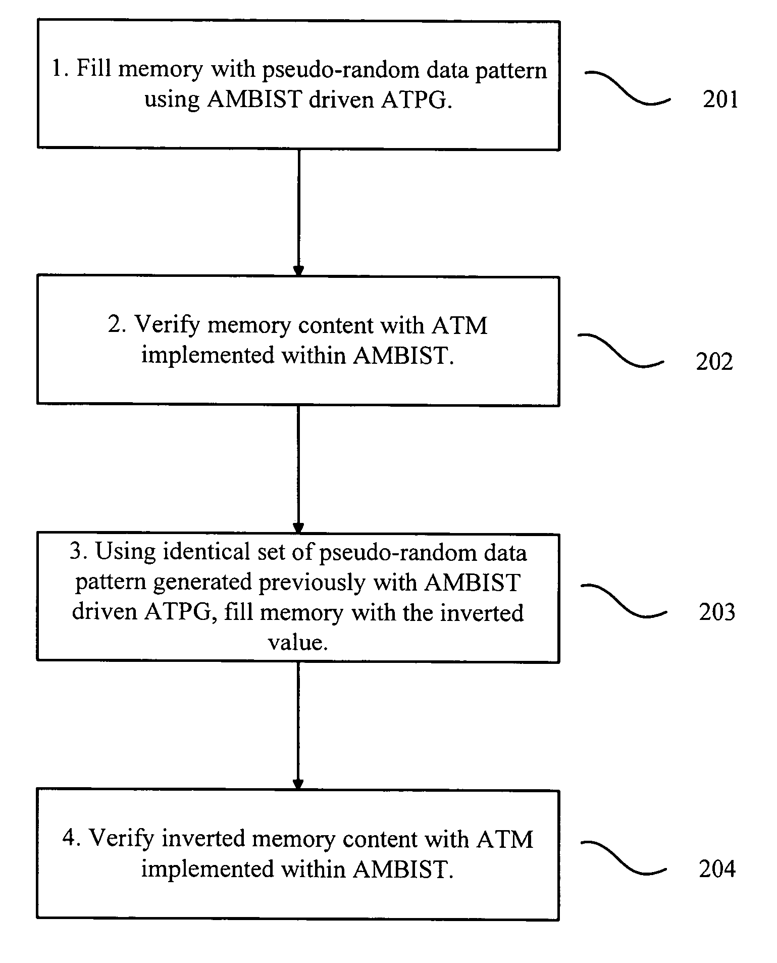
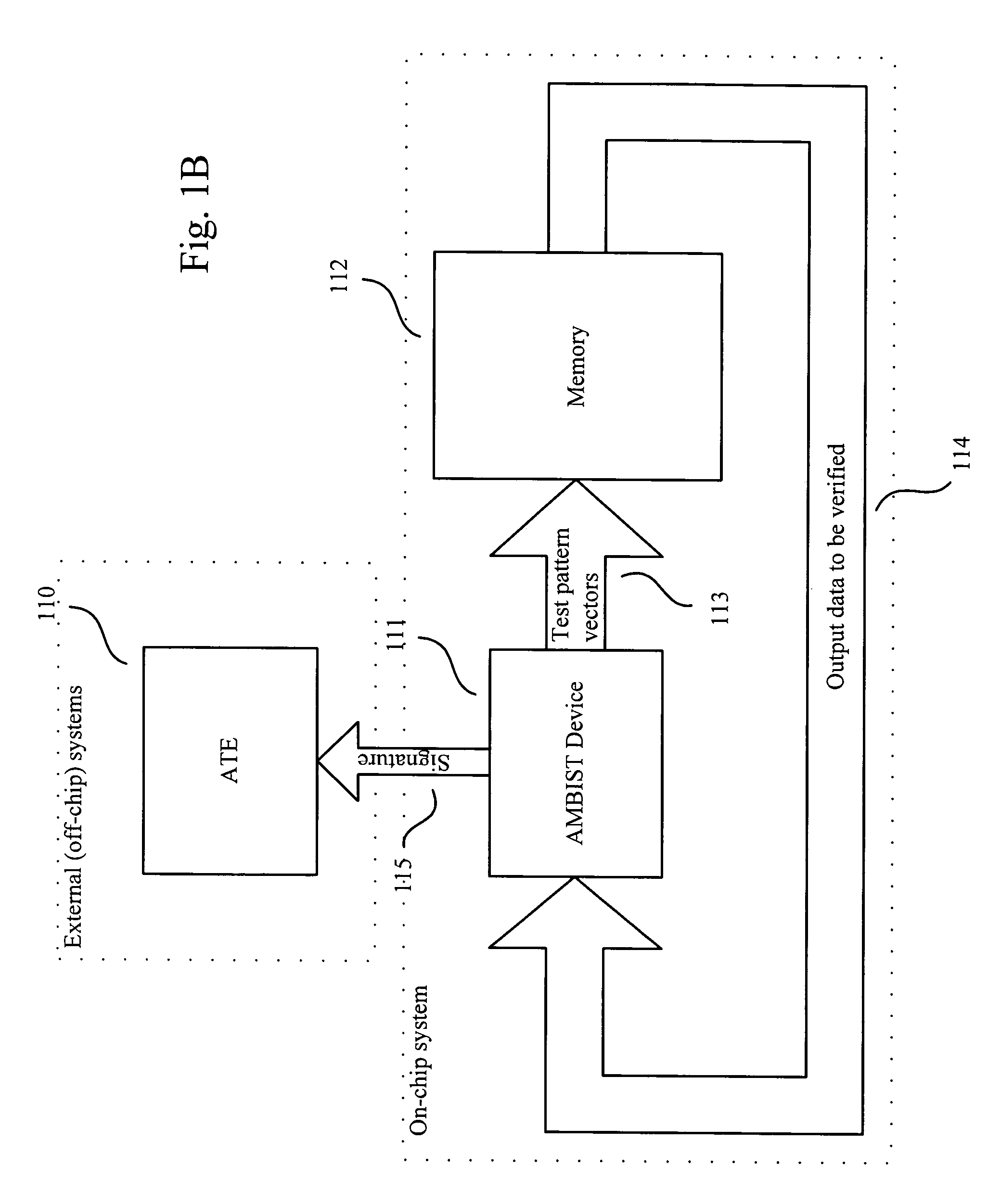
[0029] A test system and a method for testing a memory are described as follows. The test system is referred to as Accelerated Memory Built-In Self-Test (AMBIST) in the following description. Accelerated Memory Built-In Self-Test (AMBIST) system and methodology provides both Automatic Test Pattern Generation (ATPG) and Accelerated Test Method (ATM) verification solutions on a memory chip; thus, reducing test time, cost, and complexity of external test equipment.

[0030]FIG. 1B shows an exemplary memory test system with AMBIST embedded in a memory chip. In this embodiment, test pattern vectors 113 are generated with AMBIST device 111 and written into memory 112; then content of the memory 114 are rea...


PUM


Abstract

A method for testing a memory is described. The method includes the following steps. First, a test pattern is generated by a hash algorithm. Then, the test pattern is written into the memory. Next, the test pattern is read from the memory. Following that, a signature is generated by the hash algorithm using the test pattern read from the memory. Subsequently, the memory is verified by comparing the signature to a reference signature.

Description

BACKGROUND [0001] 1. Field of Invention [0002] The present invention relates to a method and a system for testing a memory. More particularly, the present invention relates to a method and a system for testing a memory using a hash algorithm. [0003] 2. Description of Related Art [0004] Semiconductor memory test systems traditionally employ an off-chip test methodology that relies on external test apparatuses—such as Automated Test Equipment (ATE)—for driving the test patterns and performing verification; FIG. 1A is an example of such a system. A memory device (101) receives test pattern vectors (103) from an external Automatic Test Pattern Generation (ATPG 100) hardware; then the output data (104) with previously written test vectors are read back by external hardware for verification (102) of the memory device. Both the ATPG (100) and the verification function (102) may be implemented in an ATE. Though this methodology has been a de-facto standard of memory testing, the cost remain...

Claims


Application Information

Patent Timeline
IPC IPC(8): G11C29/00
CPCG01R31/31703G11C29/56004G11C29/56G11C29/10
Inventor LIU, YEN-FU
Owner LIU YEN FU
Learn More