Free wire reclaimer with improved magnetic separation

Active Publication Date: 2006-04-06
ACTION EQUIP CO INC
View PDF12 Cites 12 Cited by
  • Summary
  • Abstract
  • Description
  • Claims
  • Application Information

AI Technical Summary

Problems solved by technology

Reclaiming rubber and metal wire is a difficult process because even separated chunks of wire and rubber tend

Method used


Image

  • Free wire reclaimer with improved magnetic separation
  • Free wire reclaimer with improved magnetic separation
  • Free wire reclaimer with improved magnetic separation

Examples


Embodiment Construction

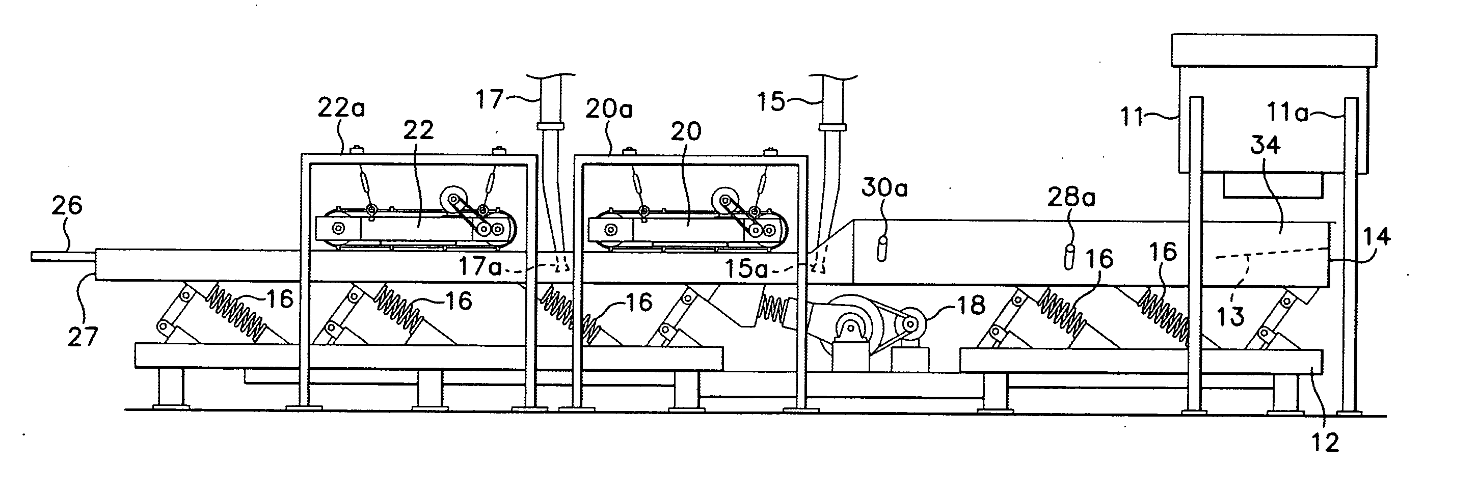
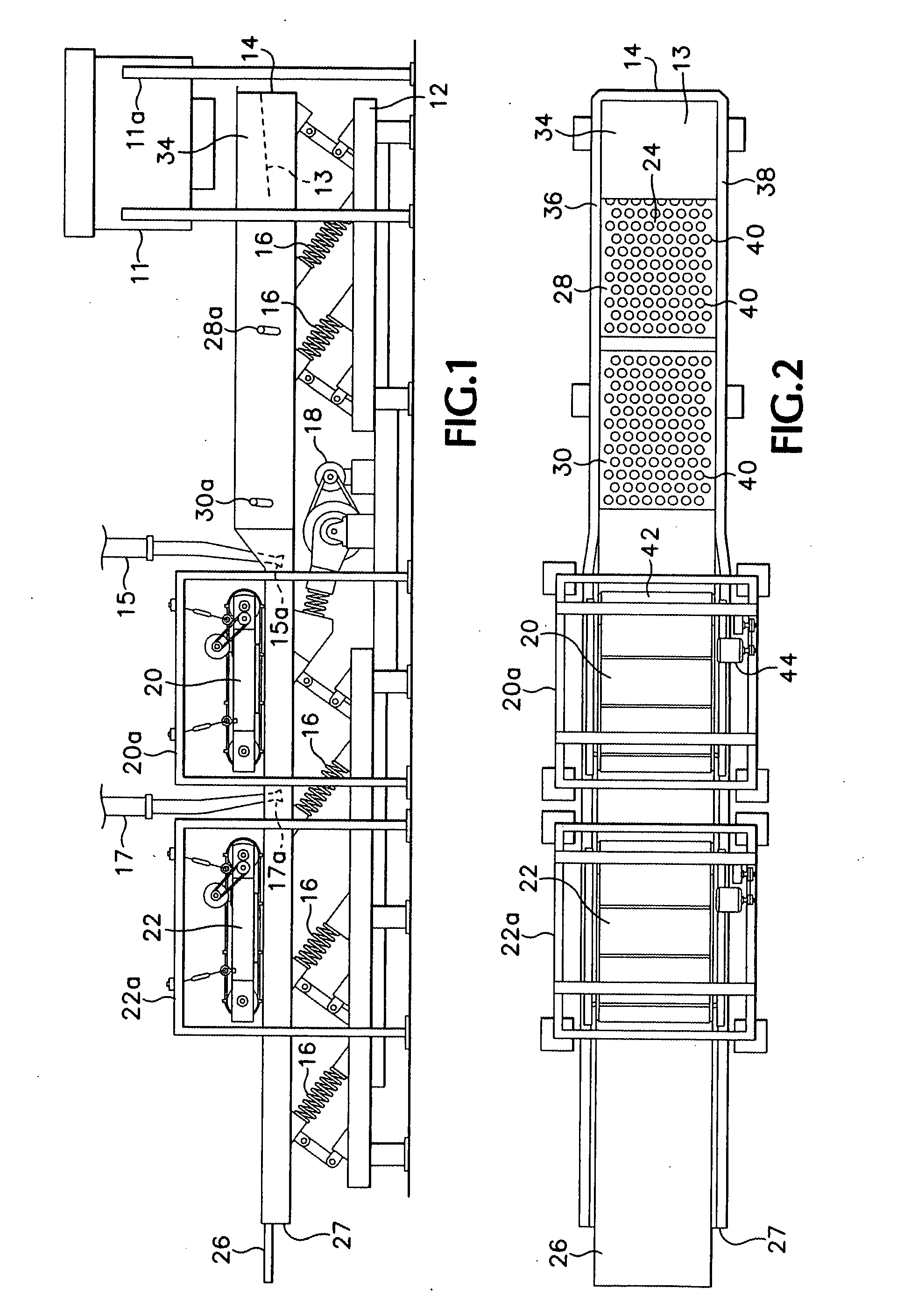
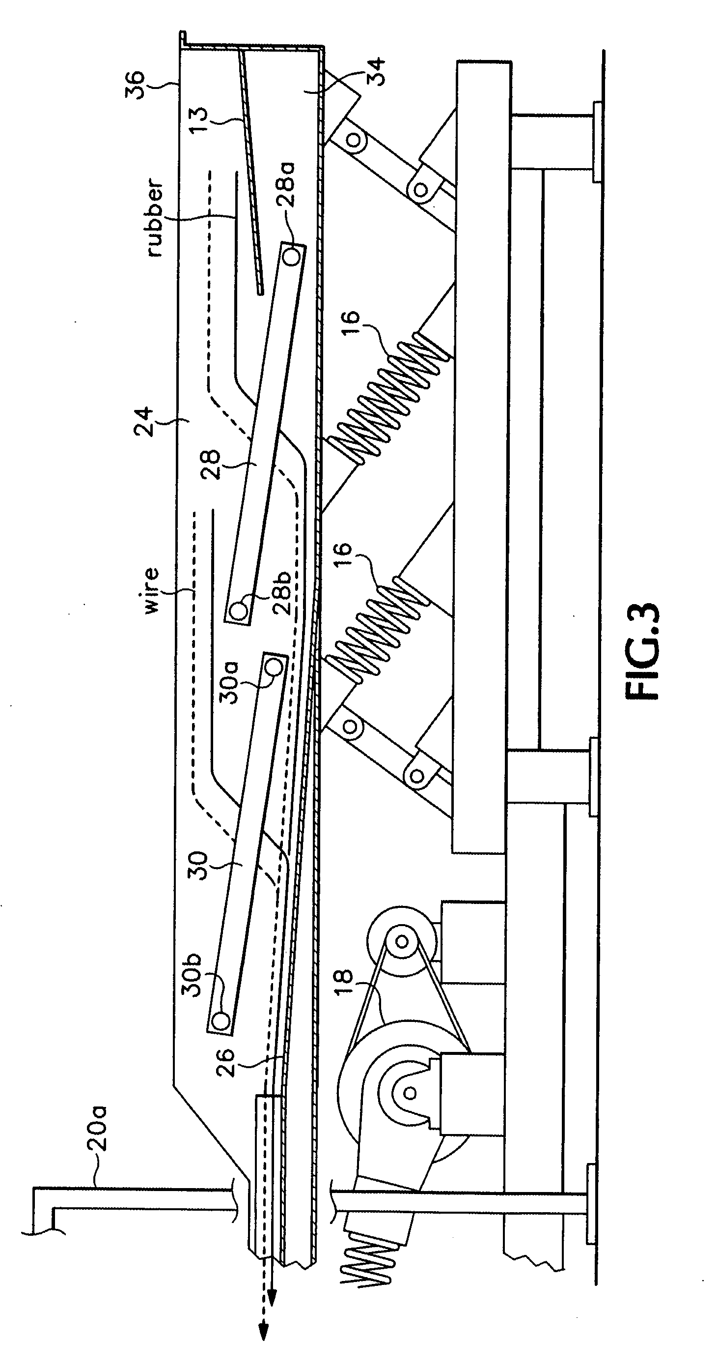
[0020] A free wire reclaiming apparatus 10 (refer to FIGS. 1 and 2) includes a frame 12 and a vibrating conveyor assembly 14. The apparatus 10 is fed by a granulator 11 supported by a frame 11a which sits astride the conveyor 14. The conveyor 14 includes a distribution plate 13 (shown in dashed outline). The distribution plate 13 is an angled plate that spreads out the product of the granulator 11 as it drops so that it is dispersed more evenly onto the conveyor 14. The vibrating conveyor 14 is a rigid unit suspended on the frame by spring assemblies 16 that allow the conveyor 14 to vibrate when driven by a motor assembly 18. The motor assembly 18 provides a linear impulse motion of a predetermined stroke length, which determines the amplitude of vibration of the vibrating conveyor 14. Action Equipment Company, Inc. of Newberg, Oreg. manufactures vibratory conveyors of this type.

[0021] A pair of magnetic separator units 20 and 22 is suspended from respective frames 20a and 22a, res...


PUM

PropertyMeasurementUnit
Angleaaaaaaaaaa
Sizeaaaaaaaaaa
Widthaaaaaaaaaa

Abstract

A magnetic separation apparatus for separating metallic material from a granulated stream of mixed metallic and nonmetallic material comprises a vibratory conveyor having a trough assembly mounted on a suspension system and coupled to a motor for causing the suspension system to vibrate. The trough assembly includes an upper trough having at least two sections aligned in a predetermined direction of material flow and a lower trough extending in the same direction as and beneath the upper. The upper trough includes one or more gaps of a predetermined width so as to permit material to fall onto the lower trough. Each trough is arranged so as to feed a different output collection point. At least one of the gaps between a downstream section of the upper trough and an upstream section of the upper trough includes the downstream section positioned at a height lower than the upstream section thereby forming a vertical drop between the two sections with the gap positioned therebetween. For each gap, an adjustable gate may be used for adjusting the width of the gap. A magnetic separator may be arranged above the gap in the upper trough so as to pick up free metal. Rubber granules fall through the gap and are deposited in a receptacle, while metal is deposited on the upper trough which feeds a separate receptacle. A declumping zone comprising at least one perforated deck may be situated in-line with the upper and lower troughs.

Description

CROSS-REFERENCE TO RELATED APPLICATIONS [0001] This is a Continuation-In-Part of pending U.S. patent application Ser. No. 10 / 345,689 filed on Jan. 15, 2003, entitled “Free Wire Reclaimer System For Scrap Tire Processors.” The specification of the above application is incorporated herein by reference.BACKGROUND OF THE INVENTION [0002] The following invention relates to a system for liberating metal in processed granulated material that may contain metal parts, such as wire, in a granulated stream of ground-up metallic and nonmetallic components, such as steel belted rubber tires. [0003] Tires are recycled by grinding and shredding the tires to form a granular stream of material. Size reduction machines grind whole tires while downstream devices called “granulators” further reduce particle sizes. Radial tires however, and in particular steel-belted radial tires, contain wire embedded in the rubber. In order to reclaim the wire and rubber in the granulated tires separately, it is neces...

Claims


Application Information

Patent Timeline
IPC IPC(8): B03C1/00B03B9/06B03C1/22B07B9/00B29B17/02
CPCB03B9/061B03C1/22B07B9/00B29B17/02B29B2017/0227B29B2017/0272B29K2021/00B29L2030/00B29L2031/3462Y02W30/52Y02W30/62
Inventor LAVEINE, ANDREW T.
Owner ACTION EQUIP CO INC
Why Eureka
Try Eureka