
Power supply controller apparatus for detecting welding of contactors

a technology of contactor welding and controller, which is applied in the direction of battery/fuel cell control arrangement, electric devices, instruments, etc., can solve the problems of high cost of circuits and wire harnesses for measuring inverter voltage vsub>inv /sub>, and the inability to fully function the entire apparatus, etc., to achieve the effect of low cost, short time, and high accuracy

Inactive Publication Date: 2006-04-06
PANASONIC EV ENERGY CO LTD
View PDF10 Cites 53 Cited by
  • Summary
  • Abstract
  • Description
  • Claims
  • Application Information

AI Technical Summary

Benefits of technology

[0023] A power supply controller apparatus in accordance with the present invention is made to solve at least one of the above-mentioned problems, and an object of the present invention is to provide a power supply controller apparatus that is low in cost and longer in its service life, and can execute welding detection of contactors with higher accuracy in shorter time.
[0027] Since the present invention allows the welding detection of the contactors without measuring the inverter voltage, circuits and wire harnesses for measuring the inverter voltage, which are required in the prior art, are not required, and as a result, the present invention is low in cost. Additionally, since the welding detection of the contactors according to the present invention is executed in only in the power supply controller apparatus, the communication with the external unit is not required, and as a result, the time required for the communication can be shortened. Furthermore, since electric charge in the capacitor is not required to be discharged for the purpose of detecting welding of the first contactor, the time required for the welding detection can be shortened. No load for discharging the electric charge is required. In accordance with the present invention, the welding detection of the contactors is executed at low cost and in shorter time.
[0029] According to the third aspect of the present invention, there is provided a program including the above-mentioned power supply control method. In accordance with the present invention, the welding detection of the contactors is executed at low cost and in shorter time.
[0031] In accordance with the power supply controller apparatus and the power supply control method, since the welding of the contactors can be detected without measuring the inverter voltage, circuits and wire harnesses for measuring the inverter voltage are not required, and as a result, the cost is reduced. Additionally, since the communication with the external unit is not required, the time required for the communication can be shortened. Furthermore, since electric charge in the capacitor is not required to be discharged for the purpose of detecting welding of the first contactor, the welding detection is executed in a shorter amount of time compared with that of the prior art. The present invention has the effect of realizing the power supply controller apparatus that executes the welding detection of the contactors at low cost and in shorter time.

Problems solved by technology

The welding of the contactors causes malfunction of the entire apparatus.
Additionally, in the case that the inverter voltage Vinv is measured, necessary circuits and wire harnesses for measuring the inverter voltage Vinv cost high.
Furthermore, in the case that the value of the inverter voltage Vinv is read out from the other electronic control unit (ECU) that controls the inverter, it takes time to communicate with each other.
It is disadvantageous to shorten the time required for welding detection.
An additional load for discharging the electric charge in short time increases the number of components, and as a result, the power supply controller apparatus becomes more expensive.

Method used


Image

  • Power supply controller apparatus for detecting welding of contactors
  • Power supply controller apparatus for detecting welding of contactors
  • Power supply controller apparatus for detecting welding of contactors

Examples


first preferred embodiment

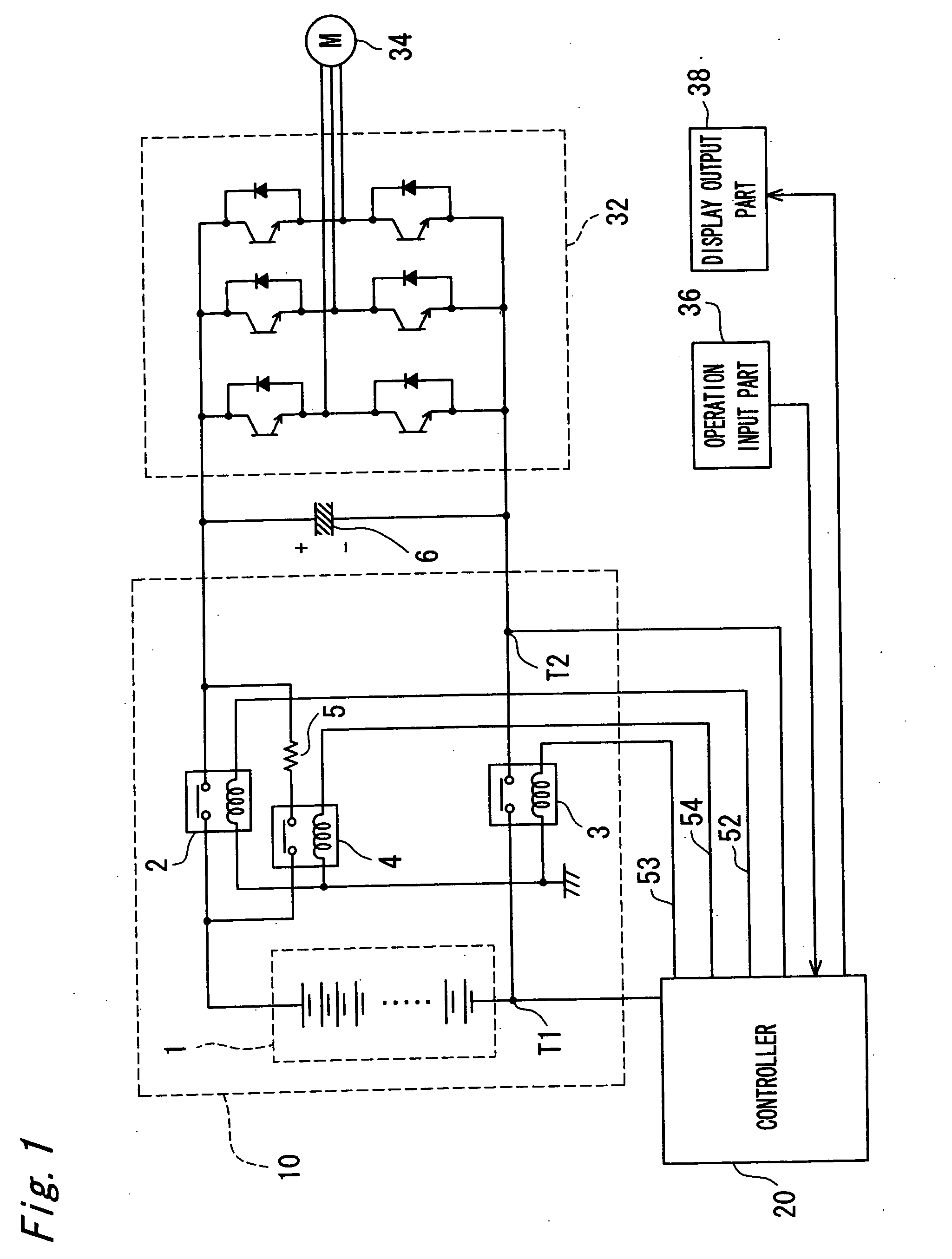
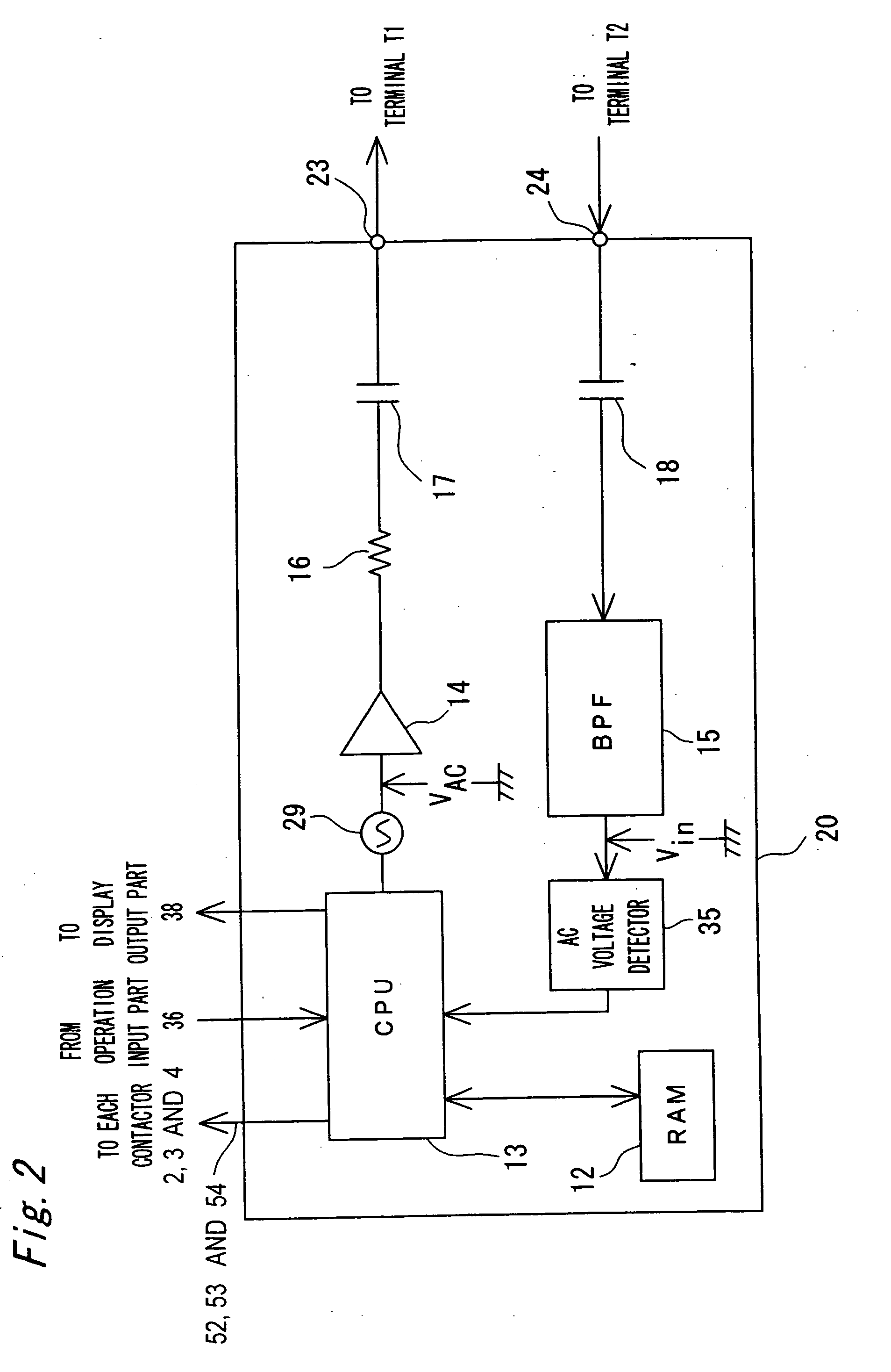
[0050] Referring to FIGS. 1 to 5, the power supply controller apparatus in accordance with the first preferred embodiment of the present invention will be described. FIG. 1 is a block diagram showing a configuration of a pure electric vehicle (PEV) having the power supply controller apparatus in accordance with the first preferred embodiment of the present invention. In FIG. 1, the pure electric vehicle includes a power supply apparatus 10, a controller 20, a capacitor 6, an inverter 32, a motor 34, an operation input part 36, and a display output part 38. The power supply apparatus 10 includes a battery assembly 1, a first contactor 2, a second contactor 3, a third contactor 4, and a current-limiting resistance 5.

[0051] The battery assembly 1 has such a configuration that a plurality of secondary batteries (e.g. 250 nickel-hydrogen batteries) are connected in series, each secondary battery has a rated voltage of 1.2V, and is a power source with a total voltage of 300V. The positiv...

second preferred embodiment

[0077] Referring to FIG. 7 and FIG. 8, the power supply controller apparatus in accordance with the second preferred embodiment of the present invention will be described. The power supply controller apparatus in accordance with the second preferred embodiment of the present invention is different from the first preferred embodiment in that the power supply controller apparatus includes a controller 620 instead of the controller 20 of the first preferred embodiment shown in FIG. 1. FIG. 7 is a block diagram showing a detailed configuration of the controller 620 in accordance with the second preferred embodiment of the present invention. The controller 620 includes a BPF circuit 65 instead of the BPF 15 of the controller 20 of the first preferred embodiment shown in FIG. 2, a CPU 63 instead of the CPU 13, and an AC voltage generator 29A instead of the AC voltage generator 29. In other respects, the configuration is similar to that of the first preferred embodiment. Components similar...

third preferred embodiment

[0094] Referring to FIG. 9 and FIG. 10, the power supply controller apparatus in accordance with the third preferred embodiment of the present invention will be described. The power supply controller apparatus in accordance with the third preferred embodiment of the present invention is different from the first preferred embodiment in that the power supply controller apparatus includes a controller 820 instead of the controller 20 of the first preferred embodiment shown in FIG. 1. FIG. 9 is a block diagram showing a detailed configuration of the controller 820 in accordance with the third preferred embodiment of the present invention. The controller 820 includes a CPU 83 instead of the CPU 13 of the controller 20 of the first preferred embodiment shown in FIG. 2, and further includes a capacitor 81 for determining the welded contactor in addition to the configuration of the controller 20 of the first preferred embodiment. The method for welding detection of the CPU 83 is different f...


PUM


Abstract

A power supply controller apparatus is provided for use in a power supply apparatus including a battery assembly. The power supply controller apparatus includes a controller that controls supplying power to a load from said battery assembly through a capacitor connected between first and second contactors by turning on and off each of contactors. The controller detects whether or not each contactor is welded based on an output signal from one output terminal of both ends of the capacitor, when the each contactor is controlled to be turned off and an AC signal is applied to one input terminal of (a) one end of the battery assembly, (b) the other end of the battery assembly, and (c) each connection point between secondary batteries of the battery assembly.

Description

BACKGROUND OF THE INVENTION [0001] 1. Field of the Invention [0002] The present invention relates to a power supply controller apparatus for use in a power supply apparatus. In particular, the present invention relates to power supply controller apparatus for detecting whether or not each contactor is welded using an AC signal. [0003] 2. Description of the Related Art [0004] In recent years, in electric vehicles such as pure electric vehicles (PEVs), hybrid electric vehicles (HEVs) or the like, the power supply apparatus using secondary batteries such as nickel-metal hydride batteries with high-energy density (hereinafter referred as to “nickel-hydrogen batteries”) or the like has been used as a power source for use in a motor or a drive source for various types of loads. The power supply apparatus for use in an electric vehicle requires a total voltage of 100V to 350V. The output voltage of a single battery (a cell), which is the minimum unit of a battery assembly constituting the ...

Claims


Application Information

Patent Timeline
IPC IPC(8): B60L11/18B60L3/00H02M7/48
CPCY02T10/7005B60L3/0023B60L11/1803B60L3/003B60L11/1864Y02T10/7061B60L2250/12B60L2250/16B60L2270/20B60L2240/527B60L15/007B60L50/51B60L58/21Y02T10/64Y02T10/70
Inventor YUDAHIRA, HIROFUMIMATSUKAWA, YASUSHI
Owner PANASONIC EV ENERGY CO LTD
Features
  • Generate Ideas
  • Intellectual Property
  • Life Sciences
  • Materials
  • Tech Scout
  • Unparalleled Data Quality
  • Higher Quality Content
  • 60% Fewer Hallucinations
Learn More