Image display unit and projection optical system

a technology of image display and optical system, applied in the field of image display unit and projection optical system, can solve the problems of limiting the size of conventional image display device, and the inability to obtain image of a wide area that human eyes are actually able to see, so as to correct the deterioration of telecentricity

Inactive Publication Date: 2006-04-06
NISHI KENJI
View PDF0 Cites 77 Cited by
  • Summary
  • Abstract
  • Description
  • Claims
  • Application Information

AI Technical Summary

Benefits of technology

[0060] A fifty-third invention for achieving the above object is the image display device set forth in any of the fifty-first or fifty-second invention, wherein the reflection surface with the curved surface is arranged at a position substantially conjugate with the retina of the eyeball and is a curved surface that corrects deterioration of telecentricity produced by the second fisheye-type optical system.
[

Problems solved by technology

As an image display device, there are many image devices available on the market like a TV, PC, Projector, video camera, cellular phone etc, but there is a limit to a s

Method used


Image

  • Image display unit and projection optical system
  • Image display unit and projection optical system
  • Image display unit and projection optical system

Examples


first embodiment

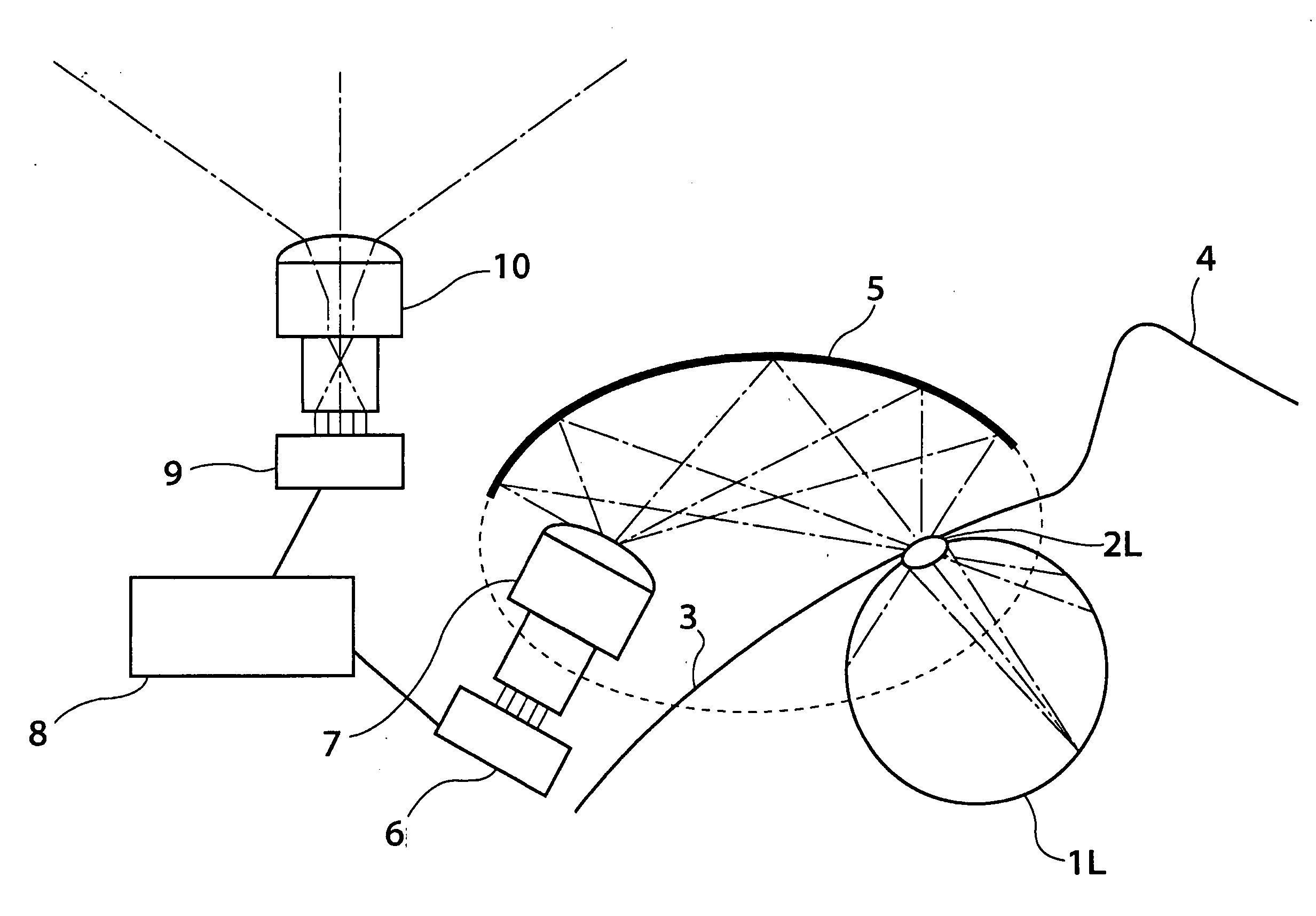
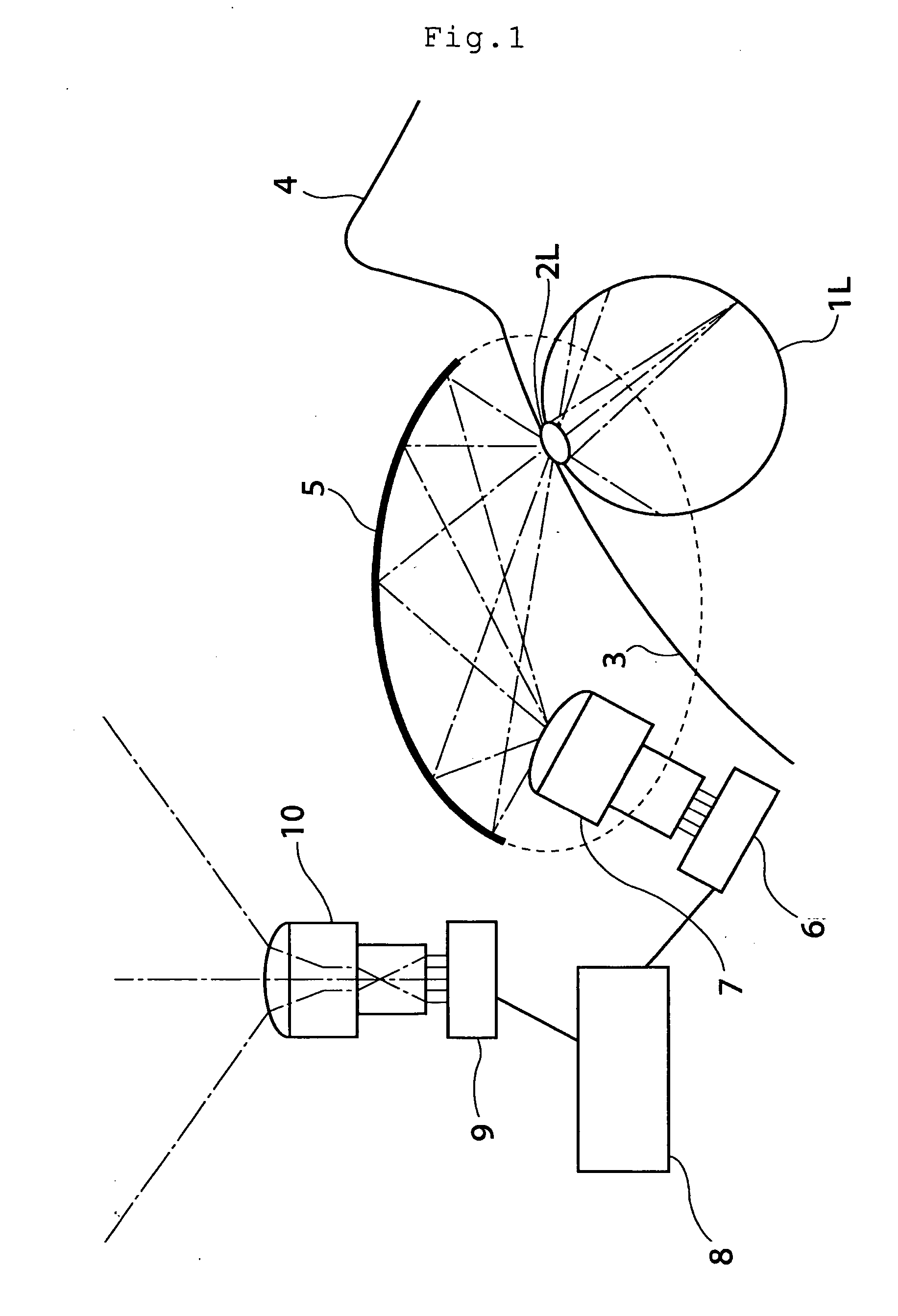
[0200] An example of a preferred embodiment of this invention will be described hereunder referring to accompanying diagrams. FIG. 1 is a schematic diagram showing this invention, wherein FIG. 1 is a cross-sectioned view taking a top view of a head of a user and shows a left side of a head, wherein contour 3 of a face, left eyeball 1L and nose 4 beside left eye crystalline lens 2L are depicted at a lower right thereof. An upper area of the figure has a broad field of view and a wide image from a broad field of view is formed on CCD two-dimensional array sensor 9 with first fisheye-type optical system 10. In this case, first fisheye-type optical system 10 has a wide angle of view and converts light flux from an object in the field of view into thin light flux, and then forms an image of the object on CCD two-dimensional array sensor 9.

[0201] A fisheye-type optical system referred to in the specifications and claims means an optical system in general that can produce a wider angle of ...

third embodiment

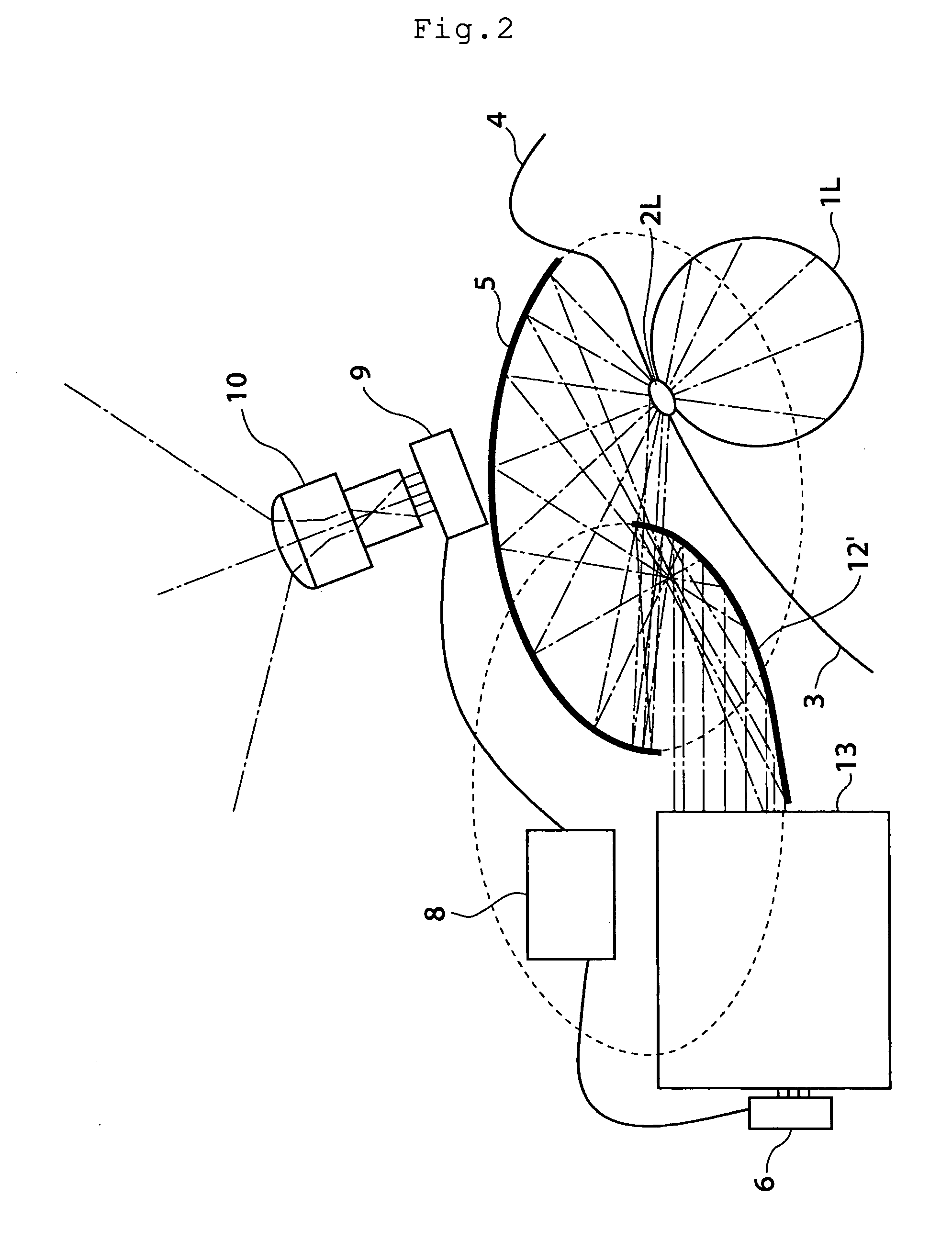
[0219] A schematic overview of this invention applying this principle is shown in FIG. 4, wherein there is a wide view area in an upper part of FIG. 4 and with first fisheye-type optical system 10, a wide image from a wide view is compressed and a projection image is formed on CCD two-dimensional array sensor 9. In this case, first fisheye-type optical system 10 has a wide-angle field of view and converts light flux from an object in the field of view into thin light flux, and thereby an image of the object is formed on CCD two-dimensional array sensor 9.

[0220] The image formed on CCD two-dimensional array sensor 9 is output to liquid crystal two-dimensional output device 6 as output image information by image processing device 8. Liquid crystal two-dimensional output device 6 is illuminated by a backlight and light is emitted from a pixel equivalent to the image in correspondence to the output image information. This light is dispersed as light flux to be dispersed again at a large...

fourth embodiment

[0224] A principle of a fourth embodiment to solve such the problem is shown in FIG. 6. In FIG. 6, to show the most ideal example, with lens 21 and spherical surface-type CCD light receiving sensor 20 that artificially duplicate an eyeball structure of a human being, a wide image is received by a CCD element inside the spherical surface as it is. As an output from image processing device 8, information output from spherical surface-type CCD light receiving sensor 20 emits a liquid crystal image intact as diffusing light flux from spherical surface-type liquid crystal device 19 that artificially duplicates the eyeball structure of the human being via lens 18 of the same performance as lens 21.

[0225] Light flux entering lens 21 is duplicated as the light flux that has the completely same optical path as one of light flux emitted from lens 18. When this diffusing light flux can be precisely duplicated on left-eye crystalline lens 2L of left eyeball 1L, information of a wide area field ...


PUM


Abstract

An intermediate image of an image from the LCD module 142 is deflected by reflection mirrors M1 and M2 via zoom automatic focus control system (g) and then is formed on diffusion glass 131 via relay lens (b) and reflection mirrors M3 and M4. The LCD image is projected on the retina of eyeballs via eyepiece lens 132 by the light flux diffused at an order of ±20 degrees by diffusion glass 131. One side of the eyepiece lens 132 close to the crystal balls 2 has an aspherical shape of a Conic surface and a Conic coefficient of the Conic surface is −1 and less. Thereby the optical system that has a viewing angle of 60 degrees and over and has a small aberration can be obtained.

Description

TECHNICAL FIELD [0001] This invention relates to an image display device that is used in proximity to at least one of eyes and a projection optical system that is arranged in front of at least one of the eyes of a user and projects an image on the eyeball of the user. BACKGROUND ART [0002] As an image display device, there are many image devices available on the market like a TV, PC, Projector, video camera, cellular phone etc, but there is a limit to a size in these conventional image display devices, so an image of a wide area that human eyes are actually able to see cannot be obtained from these image display devices. Further, as a portable image display device, an eyeglass-type image display and head-mounted image display devices that are called a wearable display device have been known. [0003] As for the wearable image display, as shown in FIG. 40, a method in which small half mirror 40 is arranged at a portion of field of view and an image output from image output element 39 s...

Claims


Application Information

Patent Timeline
IPC IPC(8): G02B13/18G02B13/06G02B17/06G02B17/08G02B27/00G02B27/01
CPCG02B13/06G02B17/0615G02B17/08G02B17/0816G02B23/18G02B2027/011G02B2027/0123G02B2027/0132G02B2027/0136G02B27/0172
Inventor NISHI, KENJI
Owner NISHI KENJI
Why Eureka
Try Eureka