Forward converter with synchronous rectifier and reverse current control

a reverse current control and forward converter technology, applied in the field of circuit controllers, can solve the problems of power efficiency, high conducting loss, and the possibility of mosfet burning down the reverse current in the circuit entirely, and achieve the effect of high conducting loss, power efficiency, and high efficiency

a reverse current control and forward converter technology, applied in the field of circuit controllers, can solve the problems of power efficiency, high conducting loss, and the possibility of mosfet burning down the reverse current in the circuit entirely, and achieve the effect of high conducting loss, power efficiency, and high efficiency

US20060072349A1Inactive Publication Date: 2006-04-06ACBEL POLYTECH INC

Image

  • Forward converter with synchronous rectifier and reverse current control
  • Forward converter with synchronous rectifier and reverse current control
  • Forward converter with synchronous rectifier and reverse current control

Examples


Embodiment Construction

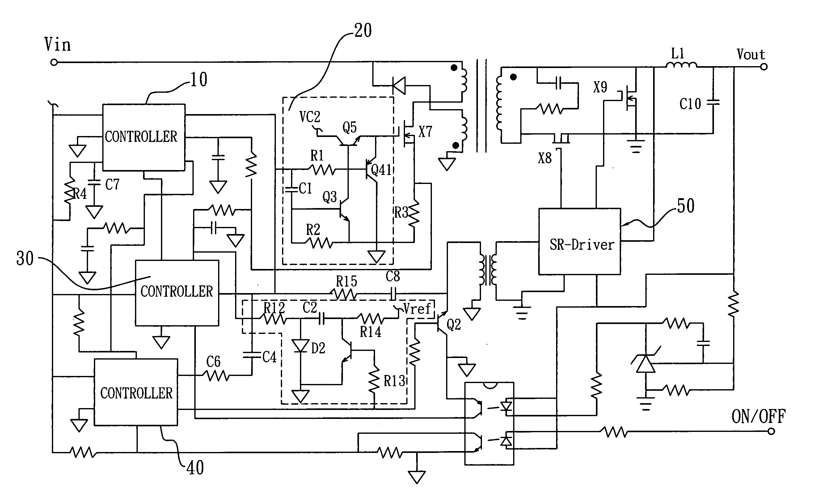
[0033] Referring to FIG. 3 of the drawings, a circuit diagram of a forward converter using a synchronous rectifier control circuit is illustrated, in which the forward converter comprises a Synchronous Rectifier (SR) control circuit comprising a PWM controller 10, a delay controller 20, a Synchronous Rectifier (SR) continue conduction mode (CCM) controller 30, a SR-on-off controller 40, and a SR driver 50.

[0034] The PWM controller 10 is used to generate driver signals for the main MOSFET, X7, and the SR circuit. The delay controller 20 is used to delay the driver signals in order to prevent the overlap between main MOSFET X7 and SR MOSFET, X8, X9. The SR-CCM controller 30 is used to control the reverse current of L1 via extending the duty cycle approach. The SR-on-off controller 40 is used to have the SR control circuit to manage the turning-off sequence. The SR-driver 50 is used to regenerate a clock signal and strengthen the driver capability. Moreover, others circuits basically ...


PUM


Abstract

A control circuit for use in a power converter having a synchronous rectifier for producing substantially direct current including a sensor for sensing a characteristic of the power converter, detection circuitry capable of using the characteristic to develop a control signal for controlling the power converter, and synchronous rectifier control circuitry connected to the detection circuitry wherein the control circuitry is adapted to modify a duty cycle of the power converter as a function of the control signal thereby to turn off a freewheel switch of the synchronous rectifier before turning off a forward switch of the synchronous rectifier during a reverse current period.

Description

BACKGROUND OF THE PRESENT INVENTION [0001] 1. Field of Invention [0002] The present invention relates to a circuit controller, and more particularly to a forward converter with a synchronous rectifier that is adapted to resolve problems of reverse current. [0003] 2. Description of Related Arts [0004] The traditional forward switching power supplies have widely been used currently, since its high current output capabilities and simplicity. In order to further improve the conducting loss of diodes and overall efficiency, Synchronous Rectifier (SR) approach is best chosen to replace the diode's function. Although the high conducting loss issue can largely be relieved with SR technique, there are other problems attached to this SR technology, which is the reverse current issue. It may occur in a number of different scenarios, such as cutting off during no load, Over Voltage Protection (OVP) testing during an Automatic Test Equipment (ATE) test, or cutting off during a dynamic test. The ...

Claims


Application Information

Patent Timeline
06 Apr 2006
Publication
US20060072349A1
IPC
H02M3/335
CPC
H02M3/33592; Y02B70/1475; Y02B70/10
Inventors
LIN, KUO-FAN