Defining logical trunk groups in a packet-based network

a packet-based network and trunk group technology, applied in data switching networks, high-level techniques, sustainable buildings, etc., can solve the problems of physical limitations on the amount of data, call disconnections, and based on the capacity of the circuit, so as to improve network resource management efficiency, increase scalability, and improve the effect of scalability

Inactive Publication Date: 2006-04-06
SONUS NETWORKS
View PDF24 Cites 180 Cited by
  • Summary
  • Abstract
  • Description
  • Claims
  • Application Information

AI Technical Summary

Benefits of technology

[0031] Implementations can realize one or more of the following advantages. The requirement of centralized control over IP routes (e.g., by a VPS) is eliminated. Additionally, knowledge of the network topology is not required to control time-sensitive data transmission through the IP network. Implementations realize increased scalability because knowledge of network topology is not required. Further advantages include controlling data through an IP network based on characteristics or parameters other than bandwidth capacity. Faster processing and more efficient network resource management is realized due to decreased data communications from a centralized control.
[0032] Another advantage includes increased visibility from the perspective of, for example, a network administrator into the IP network backbone. The increased visibility improves network management functions by allowing a network administrator to configure or manipulate call traffic through the IP network based on performance statistics. The performance statistics can provide visibility by reporting on the performance associated with various sets of pathways or calls. The performance statistics also relate to the quality of the IP network and devices used by the network.
[0033] In some embodiments, the performance statistics relate to call transmission or data transmission associated with a set of pathways. More particularly, the performance statistics allow a network administrator to track packet transmission through an IP network by only monitoring the devices that transmit and receive data packets. For example, the performance statistics can indicate whether a certain network (e.g., PSTN or IP network) is difficult to reach, which enables a network administrator to route calls around or away from the network that is difficult to reach. The performance statistics can be industry networking or traffic standard statistics such as Telcordia GR-477 or Telcordia TR-746 standard statistics that are used by PSTN administrators or individual statistics developed independently to determine network performance in IP networks. Knowledge of the packet-based network's performance allows an administrator to narrow or tailor troubleshooting efforts to improve performance to those areas within the packet-based network that are experiencing difficulty.
[0034] Another advantage associated with increased visibility includes improved ease of migration from circuit-switched telephony networks (e.g., the PSTN) to packet-switched telephony networks (e.g., IP networks) by allowing an administrator to employ similar tools for managing the IP networks as are available for managing the PSTN. One implementation of the invention can provide all of the above advantages.

Problems solved by technology

In such a configuration, the trunks impose physical limitations on the amount of data (and hence the number of calls) that may be transmitted over the trunk group.
Such limits are based on the capacity of the circuit to transmit data.
For example, the call may be disconnected or problems such as jitter or delay in voice transmission can occur for existing calls due to the increased data traffic.
Although the strict limit on the number of additional calls that a particular trunk can transmit in circuit-based telephony are not present in packet-based telephony, the network itself and the topology of the network can present practical or physical limits on data transmission (e.g., call routing or quality).
The chokepoint can result in lost or delayed transmission of data packets that affects existing calls.
When a packet-switch is a router, the router generally lacks the processor capacity and signaling capability to reroute incoming data packets to prevent further network slowdown due to the chokepoint.

Method used


Image

  • Defining logical trunk groups in a packet-based network
  • Defining logical trunk groups in a packet-based network
  • Defining logical trunk groups in a packet-based network

Examples


Embodiment Construction

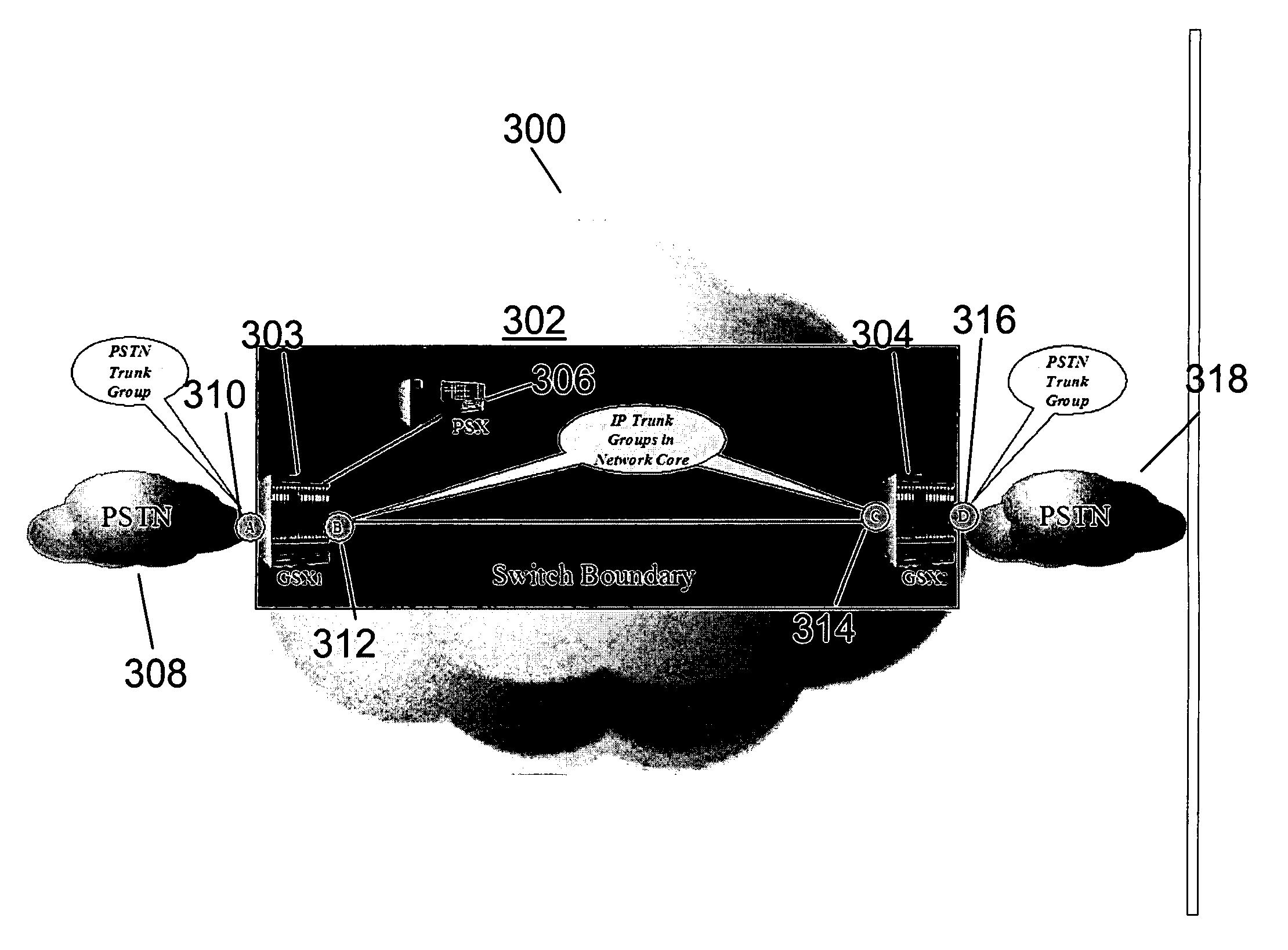
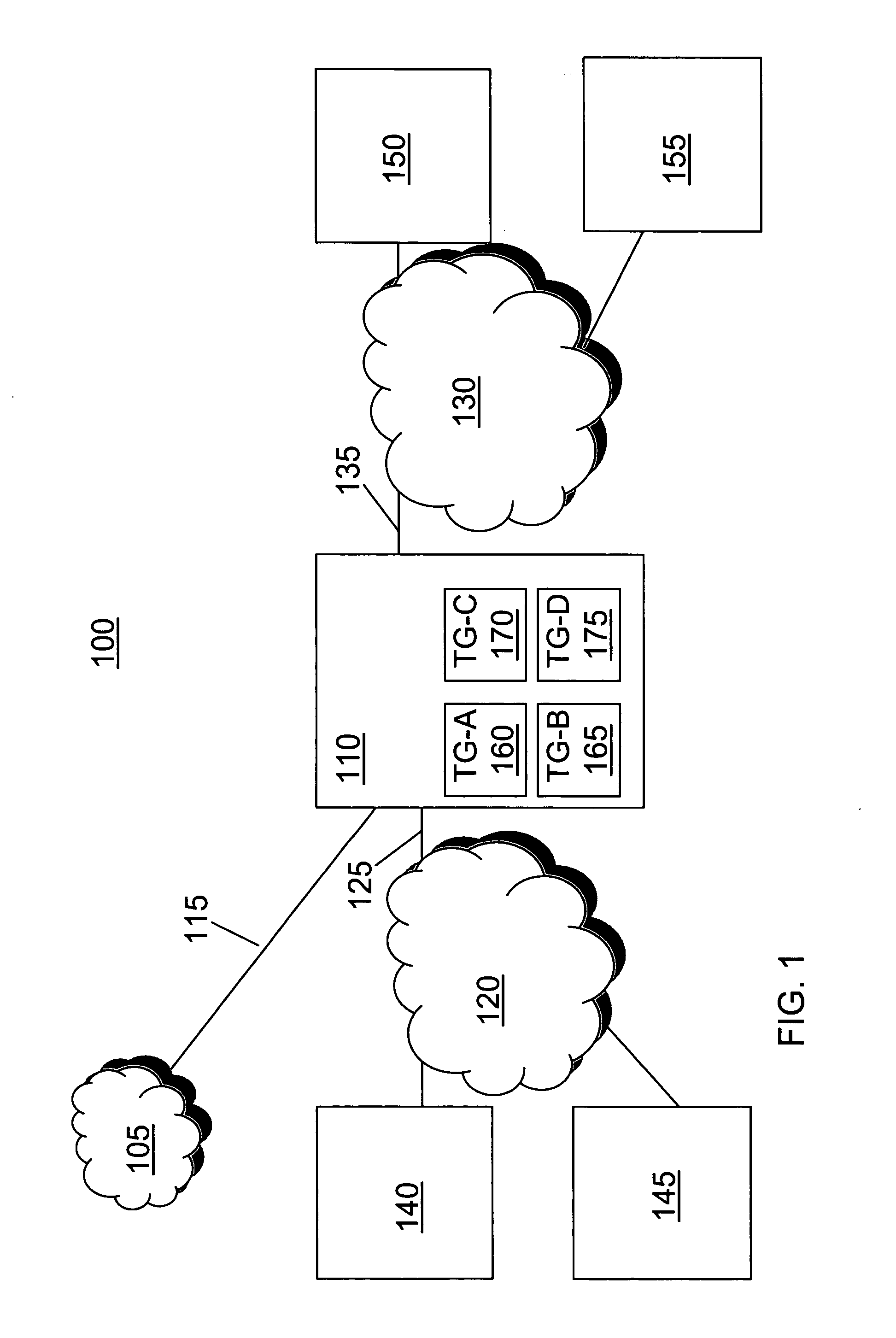
[0041]FIG. 1 depicts a system 100 that includes exemplary networks and devices associated with routing data associated with a call through a packet-based network. Data associated with a call can include one or more sets of data packets and may be referred to herein as data packets, a set or sets of data packets, a call or calls, a call leg, or some combination of these terms. Although in general, the call data described in this description is referencing media data (e.g., voice, video), the call data may also include signaling data without departing from the scope of the invention. The system 100 includes a PSTN 105 that is in communication with a media gateway 110 over communication channel 115. In some examples, the communication channel 115 includes PSTN trunk groups. The gateway 110 can be, for example, a GSX9000 sold by Sonus Networks, Inc., of Chelmsford, Mass.

[0042] The gateway 110 is in communication with a first packet network 120 over a communication channel 125. The gate...


PUM


Abstract

Described are methods and apparatus, including computer program products, for defining logical trunk groups in a packet-based network. A plurality of logical trunk groups are defined for a first media gateway in communication with a packet-based network. Each of the plurality of logical trunk groups is associated with one or more media gateways in communication over the packet-based network with the first media gateway. Data associated with a call that is received or transmitted by the media gateway is associated with a first logical trunk group of the plurality of logical trunk groups.

Description

CROSS REFERENCES TO RELATED APPLICATIONS [0001] This application claims the benefit of U.S. Provisional Application No. 60 / 614,182, filed on Sep. 29, 2004, the disclosure of which is hereby incorporated herein by reference.FIELD OF THE INVENTION [0002] The description describes defining logical trunk groups in a packet-based network. Acronyms [0003] The written description employs various acronyms to refer to various services and system components, as follows: [0004] Digital Signal Processor or Digital Signal Processing (“DSP”) [0005] Gateway-to-Gateway (“GW-GW”) [0006] Graphical User Interface (“GUI”) [0007] Internet Protocol (“IP”) [0008] Internet Service Provider (“ISP”) [0009] Point of Presence (“POP”) [0010] Public Switched Telephone Network (“PSTN”) [0011] Session Initiation Protocol (“SIP”) [0012] Signaling System 7 (“SS7”) [0013] Transport Service Access Point (“TSAP”) [0014] Virtual Local Area Network (“VLAN”) [0015] Voice over Internet Protocol (“VOIP”) BACKGROUND [0016] ...

Claims


Application Information

Patent Timeline
Patent Type & Authority Applications(United States)
IPC IPC(8): H04L12/66
CPCH04L12/5695H04L12/66H04L29/06027H04L41/08H04L41/0813H04L41/0836H04L41/0893H04L41/12H04L41/22H04L41/5012H04L41/5032H04L41/5087H04L43/08H04L43/0829H04L45/22H04L45/245H04L45/28H04L47/10H04L47/15H04L47/2416H04L47/2441H04L47/41H04L47/724H04L47/801H04L47/822H04L47/825H04L47/828H04L49/606H04L2012/5663H04L2012/5671H04L2012/6443H04M7/1205H04M7/1245Y02B60/33H04L65/1043H04L65/104H04L65/103H04L47/70Y02D30/50H04L41/34H04L41/344H04L47/43H04L65/1101
Inventor ST. HILAIRE, KENNETH R.GRIPPO, RONALD V.FARAHMAND, FARDADMATRAGI, WASSIMMENON, SUNIL K.PASCO-ANDERSON, JAMES A.STEWART, GLENN W.TEMPLETON, WILLIAM C.
Owner SONUS NETWORKS
Why Eureka
Try Eureka