Robot system with vision sensor

a robot system and sensor technology, applied in the field of robot systems with vision sensors, can solve the problems of affecting the work efficiency of the robot, affecting the operation of the robot, so as to achieve efficient measurement of errors, accurate correction, and quick performance

Active Publication Date: 2006-04-06
FANUC LTD
View PDF5 Cites 32 Cited by
  • Summary
  • Abstract
  • Description
  • Claims
  • Application Information

AI Technical Summary

Benefits of technology

[0007] It is an object of the present invention to provide a robot system having an external measuring function using a vision sensor, which is capable of quickly performing an external measuring in association with a plurality of robots, with labor spent mainly on the reattaching work of the vision sensor being lightened, and thereby capable of efficiently measuring errors in 3D relative position / orientation between individual robots and peripheral objects, so as to permit previously taught position / orientation data to be accurately corrected.

Problems solved by technology

When applying a robot work (or task) program, prepared by an off-line teaching based on a simulation, to an actual robot, actual relative positions between the robot and objects (e.g., various peripheral equipment) present in the working environment of the robot may include errors with respect to relative positions between the corresponding models in the off-line teaching.
Further, when moving an actually used robot system in position of installation, errors may arise in the relative positions between the robot and peripheral equipment during a period between before and after movement.
Such a reattaching work of the camera and image processing unit in association with a plurality of robots and robot control units is likely to spend time and thus to degrade working efficiency.
Further, the imaging camera is generally connected through a signal cable to the image processing unit, so that the handling (e.g., detaching and connecting) of the signal cable also tends to take labor.

Method used


Image

  • Robot system with vision sensor
  • Robot system with vision sensor
  • Robot system with vision sensor

Examples


Embodiment Construction

[0023] The embodiments of the present invention are described below in detail, with reference to the accompanying drawings. In the drawings, the same or similar components are denoted by common reference numerals.

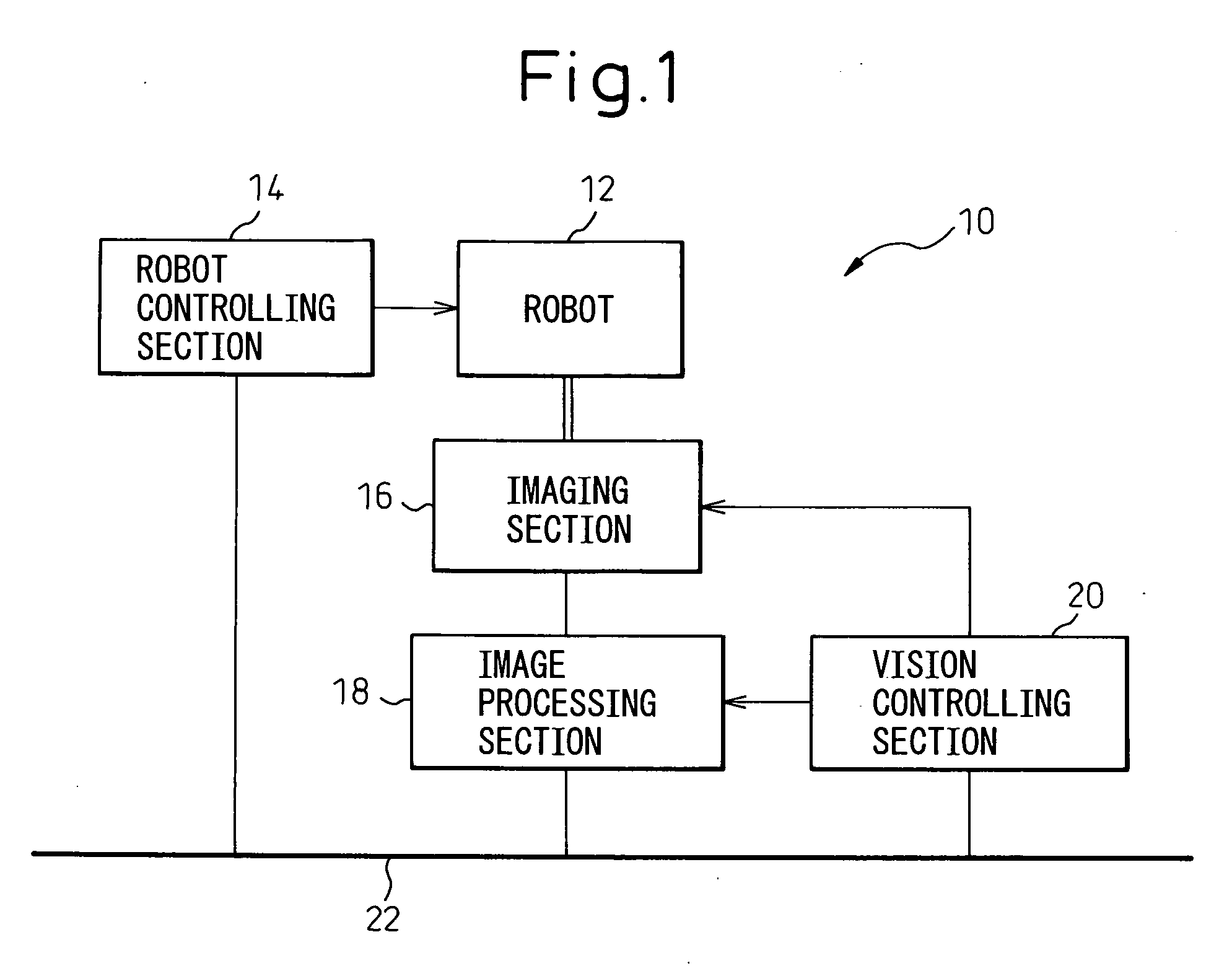
[0024] Referring to the drawings, FIG. 1 shows the basic configuration of a robot system 10 according to the present invention. The robot system 10 is provided with a robot 12; a robot controlling section 14 for controlling the operation of the robot 12; an imaging (or image pick-up) section 16 provided on the robot 12 and obtaining image data of the working environment of the robot 12; an image processing section 18 for processing the image data obtained in the imaging section 16; a vision controlling section 20 for controlling the imaging section 16 and the image processing section 18 to cause execution of obtaining the image data, transmitting the image data thus obtained, and processing the image data; and a communication network 22 to which the robot controlling secti...


PUM


Abstract

A robot system having a vision sensor. The robot system includes a robot; a robot controlling section for controlling an operation of the robot; an imaging section provided on the robot and obtaining image data of a working environment of the robot; an image processing section for processing the image data obtained in the imaging section; a vision controlling section for controlling the imaging section and the image processing section to cause execution of obtaining the image data, transmitting the image data thus obtained, and processing the image data; and a communication network to which the robot controlling section, the image processing section and the vision controlling section are connected. The robot controlling section, the image processing section and the vision controlling section are incorporated into a common robot control unit, the imaging section is connected to the image processing section through the communication network, and the vision controlling section causes a transmission of the image data obtained in the imaging section through the communication network to the image processing section.

Description

BACKGROUND OF THE INVENTION [0001] 1. Field of the Invention [0002] The present invention relates to a robot system having a vision sensor. [0003] 2. Description of the Related Art [0004] When applying a robot work (or task) program, prepared by an off-line teaching based on a simulation, to an actual robot, actual relative positions between the robot and objects (e.g., various peripheral equipment) present in the working environment of the robot may include errors with respect to relative positions between the corresponding models in the off-line teaching. Further, when moving an actually used robot system in position of installation, errors may arise in the relative positions between the robot and peripheral equipment during a period between before and after movement. In order to measure these errors in relative positions to, e.g., correct taught data, it is known to use a robot system having a vision sensor (also called as a “robot vision”). [0005] In a conventional position erro...

Claims


Application Information

Patent Timeline
Patent Type & Authority Applications(United States)
IPC IPC(8): G06K9/00
CPCB25J9/1697
Inventor HASHIMOTO, YOSHIKIENOMOTO, MINORU
Owner FANUC LTD
Why Eureka
Try Eureka