Self-expanding stent delivery system

a stent and self-expanding technology, applied in the field of medical devices, can solve the problems of unintentional withdrawal of guidewires, difficulty in delivering stents, and difficulty in delivering stents, and achieve the effect of minimizing backbleed

Inactive Publication Date: 2006-04-06
MEDTRONIC VASCULAR INC
View PDF12 Cites 145 Cited by
  • Summary
  • Abstract
  • Description
  • Claims
  • Application Information

AI Technical Summary

Benefits of technology

[0020] Other aspects of the present invention include, but are not limited to, using different types of guide members with a catheter of the present invention, a stop to keep the stent from moving proximally as the distal outer shaft is retracted, maintaining a distal inner shaft in a distal position, such that the entire catheter is not retracted when distal outer shaft is retracted, radiopaque markers, and a valve relief to minimize backbleed as the catheter is moved into and out of the vasculature.

Problems solved by technology

Although the RX catheter may provide the advantages discussed above, it presents several difficulties.
Further, it is not possible to exchange guidewires with a RX catheter.
A guidewire exchange may be needed when, for example, the guidewire becomes damaged during the procedure; a different shape, length, or size of guidewire is needed; and / or the guidewire is unintentionally withdrawn.
At the proximal end, the RX catheter and the guide wire extend side-by-side from the body of a patient, making it awkward to seal the system against blood loss during manipulation of the components.
Further, the lack of a full-length guide wire lumen in a RX catheter deprives the clinician of an additional lumen that may be used for other purposes, such as pressure measurement, injection of contrast dye distal to the stenosis, or infusing a drug.
Heretofore, self-expanding stent delivery systems have incorporated either OTW or RX catheter systems, and clinicians have experienced the difficulties described above with respect to both OTW and RX catheters.

Method used


Image

  • Self-expanding stent delivery system
  • Self-expanding stent delivery system
  • Self-expanding stent delivery system

Examples


Embodiment Construction

[0048] The present invention is now described with reference to the figures where like reference numbers indicate identical or functionally similar elements. Also in the figures, the left most digit of each reference number corresponds to the figure in which the reference number is first used. While specific configurations and arrangements are discussed, it should be understood that this is done for illustrative purposes only. A person skilled in the relevant art will recognize that other configurations and arrangements can be used without departing from the spirit and scope of the invention.

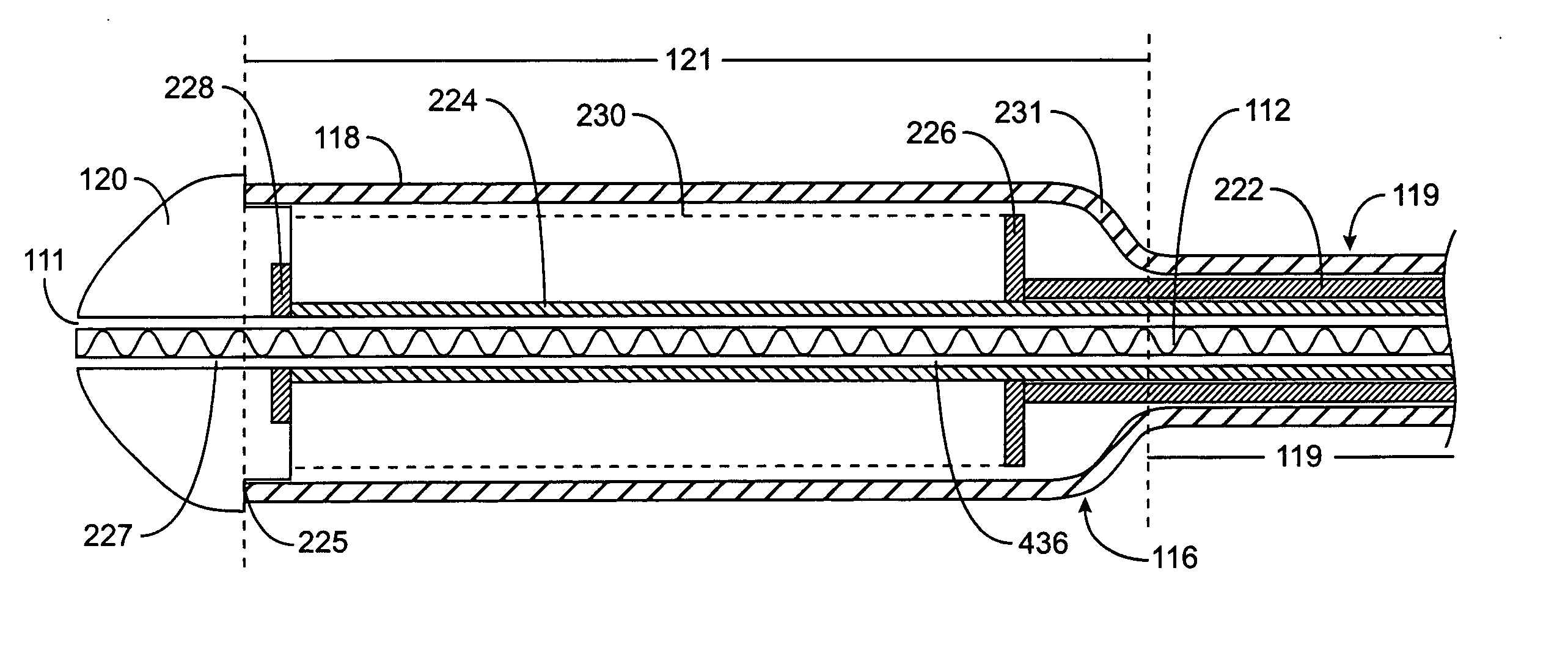
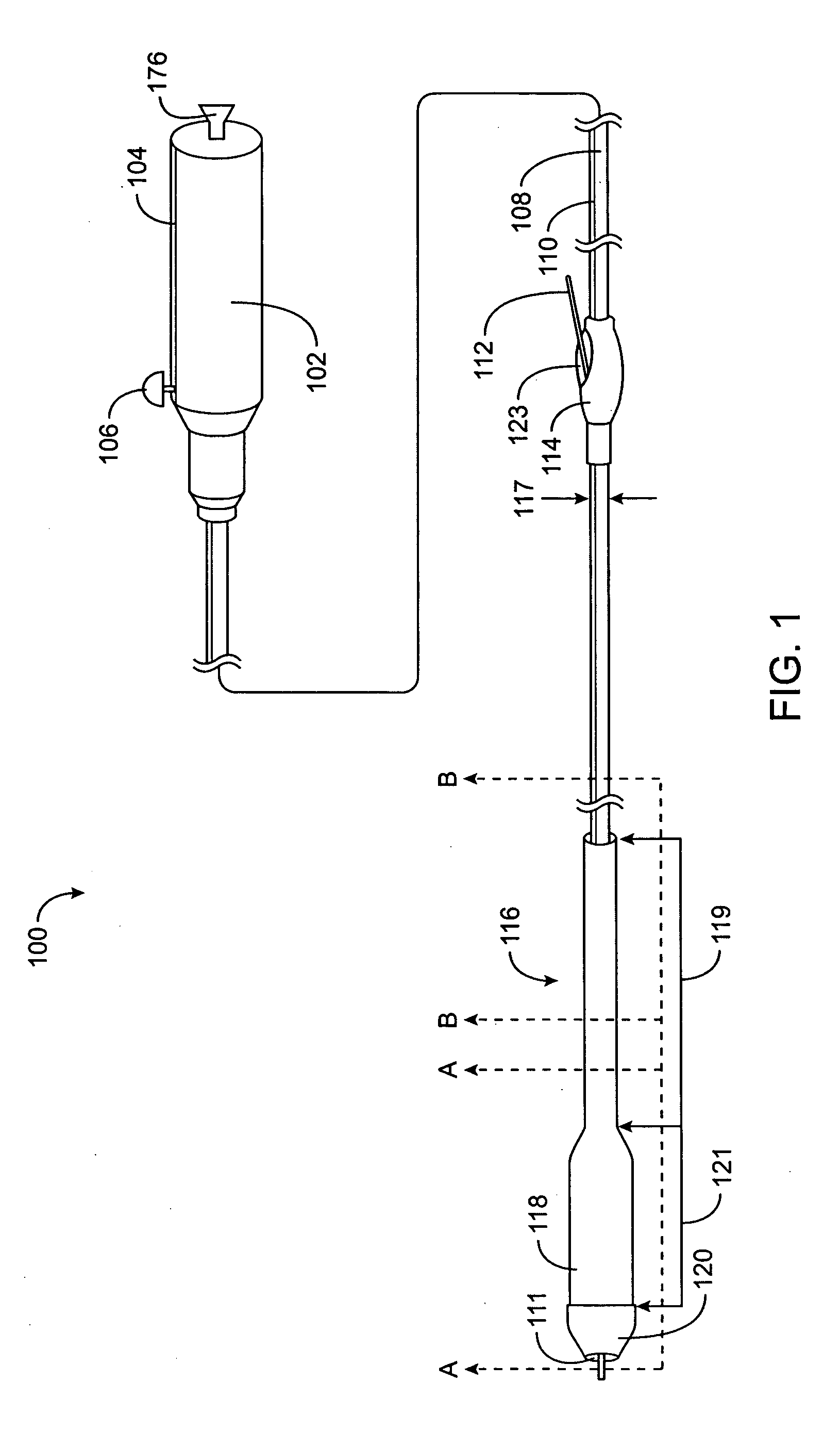
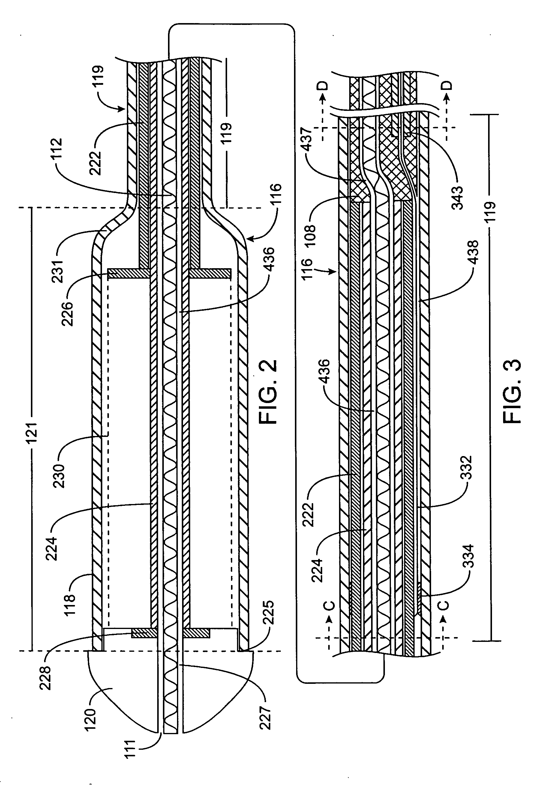
[0049]FIGS. 1-3 generally illustrate an embodiment of a self-expanding stent delivery catheter 100 according to the present invention. Catheter 100 includes at least a handle 102, a proximal shaft 108, a distal outer shaft 116 coaxial to and capable of sliding over proximal shaft 108, a link 332 between handle 102 and distal outer shaft 116, and a self-expanding stent 230 retained in a collapse...


PUM


Abstract

A catheter for a self-expanding stent includes a proximal shaft with a longitudinal guide way along the length of the proximal shaft, a guide member for accessing a guidewire lumen defined by the proximal shaft and for drawing a guidewire into and out of the guidewire lumen along the proximal shaft. In one aspect, the catheter includes a proximal sliding mechanism coupled to a link, which is coupled to a distal outer shaft retaining a self-expanding stent in a compressed state. The sliding mechanism draws the link proximally, which draws the distal outer shaft proximally thereby allowing the stent to radially expand. In another aspect, the proximal sliding mechanism is coupled to a proximal shaft, which is coupled to the distal outer shaft. The sliding mechanism draws the proximal shaft proximally, which draws the distal outer shaft proximally to thereby allow the stent to radial expand.

Description

FIELD OF THE INVENTION [0001] The present invention relates to a medical device. More specifically, the invention relates to a catheter, which includes a multi-exchange (MX) component and stent delivery system. BACKGROUND OF THE INVENTION [0002] Cardiovascular disease, including atherosclerosis, is a leading cause of death in the U.S. One method for treating atherosclerosis and other forms of coronary narrowing is percutaneous transluminal coronary angioplasty, commonly referred to as “angioplasty” or “PTCA”. The objective in angioplasty is to enlarge the affected coronary vessel from within by radial expansion. The procedure is accomplished by inflating a balloon of a balloon catheter within the narrowed lumen. The balloon expands in the coronary vessel in several different radial dimensions and opens the vessel based on the nature of the plaque. For example, soft, fatty plaque deposits are flattened by the balloon, while hardened deposits are cracked and split to enlarge the lumen...

Claims


Application Information

Patent Timeline
Patent Type & Authority Applications(United States)
IPC IPC(8): A61F2/06
CPCA61F2/95A61F2/966A61F2002/9517A61F2/9517
Inventor BERTHIAUME, WILLIAM A.COLLINS, CHRISTOPHER T.TRAN, DONBARAJAS-TORRES, MARTHA
Owner MEDTRONIC VASCULAR INC
Why Eureka
Try Eureka